|
If lashing the cheap poi-balls onto the ends of my PVC pipe was
Chapter 1 in this evolving saga, then Chapter 2 had to be those crazy
hacked-together assemblies with the dowels run into the ends of clear
polycarbonate tubing -- which I'd specifically acquired with the idea
of more advanced flow-prop building in mind, of course.
Despite holding up surprisingly well under the abuse of providing
entertainment at the weekly beachfront drum-circles down south, those
modules made from components out of cheap toys were already starting to fall
apart and it was time to think about something not only a little more
robust, but also more versatile in terms of light patterns.
There are plenty of commercial options available in this regard
but I didn't want to just spring for something off-the-shelf, it
wouldn't have the same design uniqueness that I might be able to add.
The "Chapter 2" kludgery had given me some ideas of what would work, and the folks at FlowToys had recently introduced their new LED Capsule product which was available for sale a la carte. A quick look at the patterns chart for it told me this was the sort of thing I wanted as a starting point. It also runs from a USB-rechargeable lithium cell, so I wouldn't be burning through six-packs of button cells just to, so to speak, keep the lights on. A quick emailed query clarified that although their Capsules as built wouldn't fit down my thicker-walled tubing, the working *innards* of same would, and quite neatly so. That would be fine since immediate modifications would be the essential idea! After a bit of an uphill fight with their website I managed to place an order for a couple of Capsules and a pair of their end-caps, which are much more elegant and protective than old poi-ball shells weirdly squashed by sending screws through them. The intended mods would just be adding more LEDs and adapting the mechanical fit, nothing much more than that. Plenty of people are slaving away night and day over the question of *how* to make LEDs blink in ever more sophisticated ways, so none of this would involve sitting down at an Arduino dev-kit or the like and trying to make it run patterns. I was happy to build upon the work of others who were already far better at that than I would likely ever be. My challenge would be more toward durability, e.g. repackaging something with small electronics and then repeatedly whacking it on the ground and having it *not* break. And ideally, to do so using whatever parts I could scrounge up out of my existing junkboxes and remaining stock of cheap blinkie-toys. I opened up a capsule and just stared at the extracted innards for a long time, sometimes eyeballing various dimensions against a section of my tubing, while trying to figure out what I really wanted to do. I cycled the batteries all the way down and back to full charge, generally good to do at least once on fresh cells even if lithium chemistry doesn't have the time-honored memory problem. I played around with the modes and sub-modes listed on the instruction sheet, all very well and good, but it took a while to get a clear vision of where to head on the modification project as a whole. In the meantime, I also started a little analysis of what I had here -- determining how the unit worked, where to attach external power from a variable supply, and scoping various points to learn more about its internal operation. It seemed to be a rather elegant design, more details of which are described down at the end of this page. |

|
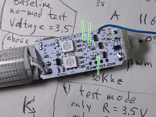
This is the output side of the Capsule board, if you will, where the LED driver transistors are. Common positive from the battery runs to all the inward anode leads on the LEDs, in the same general configuration as the boards on the cheapo toys I'd already taken apart. This is typical because it's easier to switch the negative from a non-inverted microcontroller ouput. It took a while to determine the circuit paths of what I needed to access, as the solder masking is opaque white rather than clear, but holding the board just at the right angle under light showed substantial lands coming from the collectors of the three output transistors which would be where I'd need to attach my feeds. |
| In this design, each individual LED element gets its own dropping resistor, which when driven by a minimum 3.5V power supply needs to be less than 100 ohms. They're not even running the full current capability of these 5050-style LED chips, but only at 10 or 15 milliamps they are nontheless, as Adafruit puts it, eyeball-searingly bright. They're the same ones used in a lot of the flexible strip lights on the market now. Kind of amazing how such a tiny die with a tiny bonding wire can produce *that* much light, only getting mildly warm in the process. The LEDs I would add wouldn't be nearly as punchy, but would serve to add more light-emitting area farther along the staff. I figured I could get away with ganging pairs of each color with a single dropping resistor per pair, as the forward voltage per color seemed well enough matched. | |
|
The tap wires look pretty massive on that scale of things; I could have
conceivably used something thinner like bits of Kynar, but I wanted
these to be *stranded* for the extra flexibility and they were
pretty much the smallest workable gauge I had on hand.
Their next stop would be the added resistors over next to the battery,
so they'd pass through where the whole assembly can bend a little
between the board and the battery.
Even with the whole thing eventually constrained inside tubing, a
little motion would still be quite possible during spinning [and
inevitably dropping] and I wanted everything that went through that
area to stay flexible.
On one of the two Capsule units I had done the nominally safe thing and disconnected one side of the battery, so I wouldn't have to work on the circuit hot. I could also then experiment with different supply voltages from an external variable source. But the insulation on that miniscule wire got a little mucked up in the process of desoldering, which I had to patch up while putting things back together, and I decided to *not* do that on the other unit and just keep it live during the whole modification process. I had also slid one of the chip LEDs off the board to play with it in isolation and view the routing underneath, and had to tack that back on. Despite sullying their gleaming white solder-resist here and there with ugly patches of flux, amazingly enough I did not end up with a mess of charred junk in the end. Next, it was time to dig up and prepare the other parts. I'm not a surface-mount house by any means, although as of this writing there are a couple of things on the shopping list toward better capability in that area. For this I'd just be using generic thru-hole parts and old-skool hand wiring. There's certain benefit in sticking with what we know and are handy with, even if it makes the results a little chunkier. |
|
I had decided to reverse the mounting direction of the entire works
from the way it goes into Flowtoys gear, putting the battery out at
the end and the switch toward the inside.
The switch was actually one of my harder problems; should I un-mount
what they had and supply my own button somehow, or try to arrange things
so a small tool could go in through a hole to activate it, or what?
After inordinate angst over this and picking through the junk hoard
I half-formed a workable idea: keep their switch as built and mount it
toward the inside, and have some sort of sliding piece connected to the
exterior of the tubing that would somehow push the button.
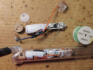
The magic piece, seen in the next few pictures, was a clear plastic part taken from the light-spreaders inside those little LED candelabra-size light bulbs. Not even sure why I had two of these around, but they were just under 3/4" diameter and a perfect sliding fit inside the tubing. Oriented a certain way, the piece could come down over the Capsule's switch board in just the right way and press the button. As the LED clusters came together and I had a better idea of where all the parts would need to sit, the design of my "switch slider" clarified. A cluster would mount right on the slider and move along with it, pointing down into the staff to provide the extra shot of light toward the center that I wanted. |
|
The output feed wire slack got rerouted to use some of the empty volume over
the board but not interfere with the LED output, and once the resistors
were taped down and the wiring carefully laid in between them, everything
slid into the "test tube" more neatly.
It was still tight, and to get the module back out I had to push
on the other end with a length of conduit [so as to encircle and not
mash the LEDs on the switch-end cluster].
In retrospect one could argue that I should have ordered in some eighth-watt parts, but what I had is what I had ... |
|
The clear plastic bracket sort of thing around the end is the clip from
the inside of the Flowtoys
end caps.
Another elegantly designed part of their kit, these lock the caps into
a pair of holes near the ends of all their 1" outside-diameter tubes,
in a way that's very easy to snap on and off.
They'd do the same on my thicker-wall stuff, with the difference that the
nubs would also retain a pin of *just* the right length run through
my tubing and the wooden spacer block, thus serving double duty.
The pin would protrude only half the wall thickness into the inside of
the tube, locking the wood in place but leaving depth for the clip nub
on the outside.
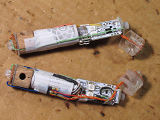
The bits of wood, more of the same 3/4" dowel as used in Chapter2, had undergone some other ridiculously subtle bits of design: a relief pit for the positive-feed bump in the cluster wiring was needed, and the tiny hole and a parallel channel down the outside were to accomodate a long loop of the green Kynar wire that would stretch all the way down to the switch board and help hold the entire assembly longitudinally together. Otherwise, I thought, the board might drift away from the battery and interfere with the throw of the switch actuator. I didn't have the luxury of custom-molded housing parts like in the original Capsule to hold everything precisely in position, so I'd have to make do. | |
|
Finally my augmented assemblies were all together and buttoned up and in theory, now ready for insertion. There was still quite a bit of other work to be done first, though ... |
|
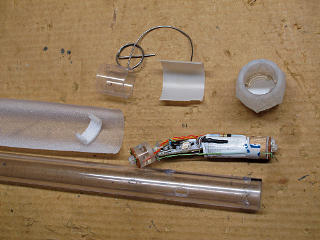
So here we have all the parts to go into an end. The semi-sparkly diffusion membrane came out of a kids-toy sword and had already been used in the previous incarnation, along with small bits of white foam to diffuse side emission from the LEDs. The development of the switch actuator was still in progress, shown by the not-quite-finished spring and sliding sleeve piece. A supplemental diffusion layer made from a section of milk-jug would encircle the Flowtoys module and its LEDs. And a small bit of white paper got stuffed into the end-cap, to try and redirect light from the end cluster out toward the sides rather than out the end of the staff where it wouldn't be as readily seen. |
| This was a lot to put together at once, and it had to go in the right order. The diffusion and foam pad went in first and only just so far down, so that the slider's LEDs would just poke into it at rest. The spring around the actuator sleeve needed to be pulled open just enough to pass down the outside of the tubing, without stretching my hand-bent spring back too far, and be cocked and ready to drop into the inner sliding piece. |
|
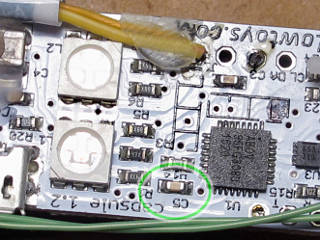
The microcontroller is an "Abov" 8051 knockoff from Korea, for which the documentation is freely available. The notes that come with the Capsule mention a very rare chance of a software lockup or crash, mostly due to static discharge, and offer the way to get out of it and reset the processor as simply shorting the battery leads for a very brief moment. Sure, that'll work, but shorting a lithium battery is never really a great idea. Here's something much gentler which has the same effect: short this tiny little capacitor at C5, which grounds the actual "RESETB" input to the chip and hard-restarts it at address 0000 just like initial power-up would. In that first-powered-up state there are a few interesting modes one can cycle through, such as full-on red/green/blue tests, full white, and one that checks the battery voltage thresholds [discovered by varying an external power supply feeding the one on the bench]. |
|
The light angle in this shot, sort of grazing the board, shows the best
way I had to determine where the circuit traces actually go by looking
at the subtle humping-up of the mask over the copper.
The masking is opaque, so the common trick of shining a light through
the fiberglass doesn't work either.
Here are some other fun facts about the design.
It's certainly not a full reverse-engineer or anything, there's no
point in trying to do that and the "security" fuse is probably blown
to lock the code anyway, but just observing some of these points had
me really respecting some of the things the Capsule designer had done
and thought of.
|