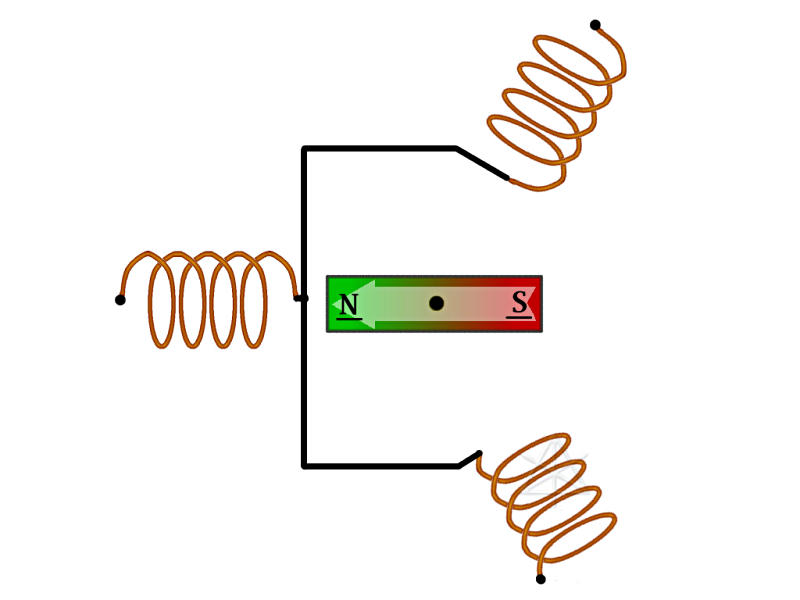
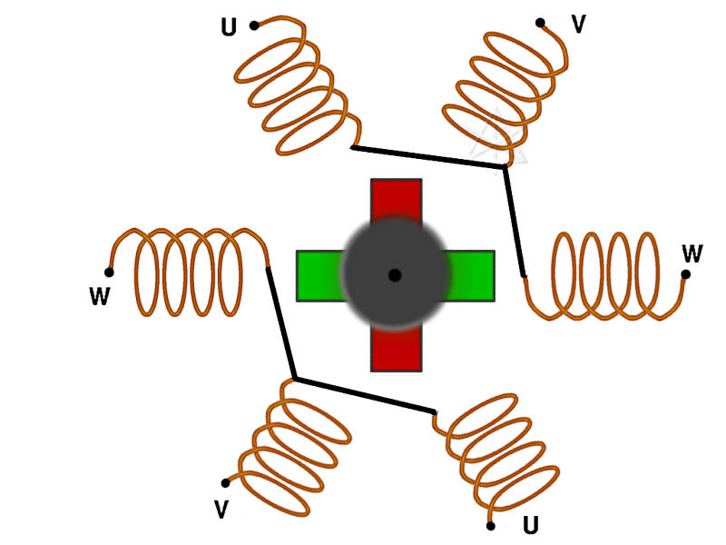
Rudimentary motor layout
Three wire coils
Bar magnet spinning on a pivot
Think "school science fair"
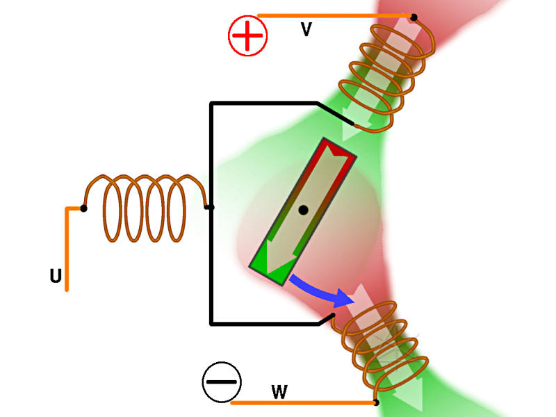
Energize one coil
Current creates magnetic field
Field aligns along coil axis
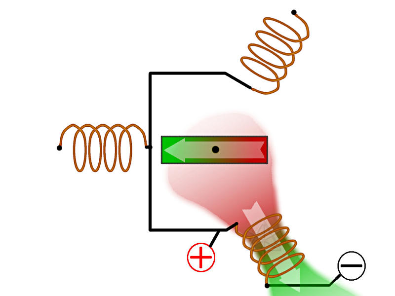
What happens to the magnet?
Opposite poles attract
Similar poles repel
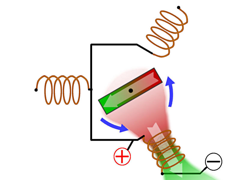
Turning force exerted on magnet
Common center is internal only
So we don't really have access to it
Attach the orange wires
Different labeling schemes:
U/V/W ; A/B/C ; ...
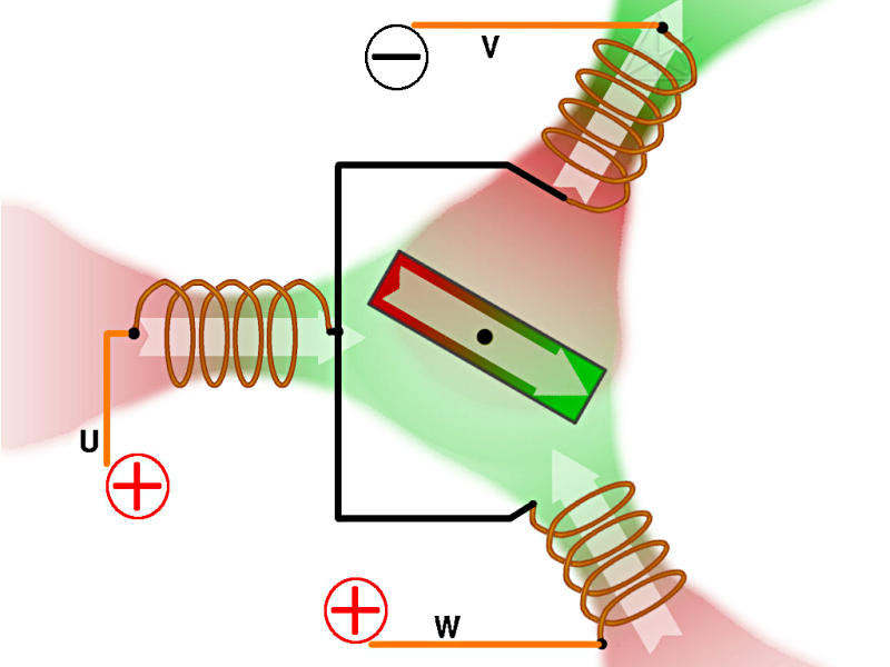
Now we energize two coils at once
Doubles force w/ same current
Now, the V coil is useless
Still have contribution from the W coil
But V coil wants to hold the red back
What do we do now?
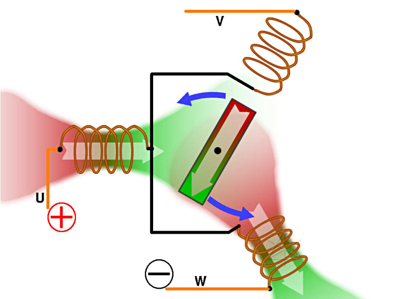
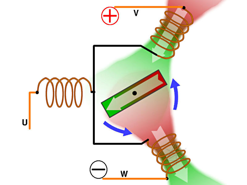
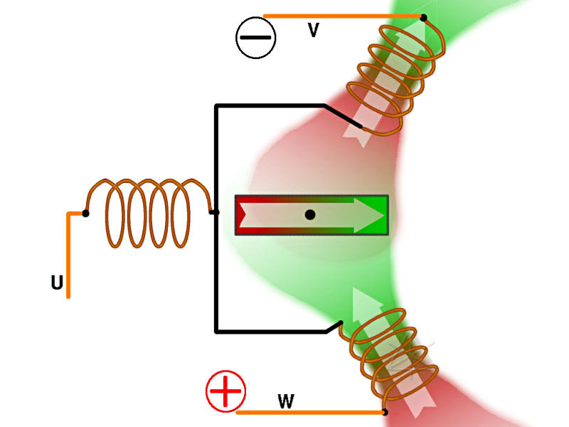
Answer: switch coils
Move (+) from V to U
New field builds from new direction
More torque to keep going
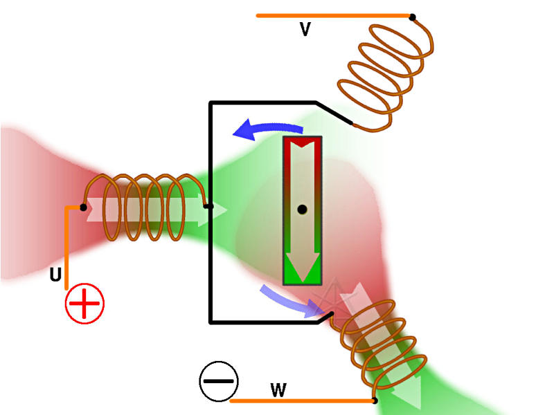
W field contribution weakens
Need to switch again soon...
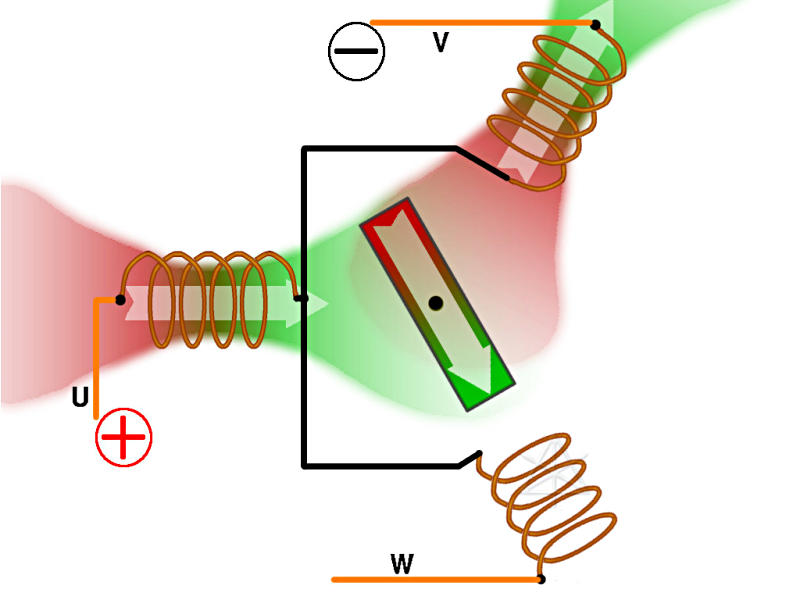
Now, move (-) to V
Maintains rotating field, high torque
Always about 90 degrees to magnet
If we're on sinewave line power instead ...
Currents build fields smoothly
All three coils carry current, except at zero-crossing
Currents into and out of motor add up to zero
Alternate switching scheme
Fire all three coils when appropriate
Current splits equally through U and W
Two half-strength north/green fields for a while
Exact opposite of where we started
V and W now reversed
U is about to swing (-)
Waveform options
Commercial power is already AC
Switching method can "fake" a sinewave
Close enough to work well, anyway
Magnetic field still rotates
How do we get all that from a DC battery?
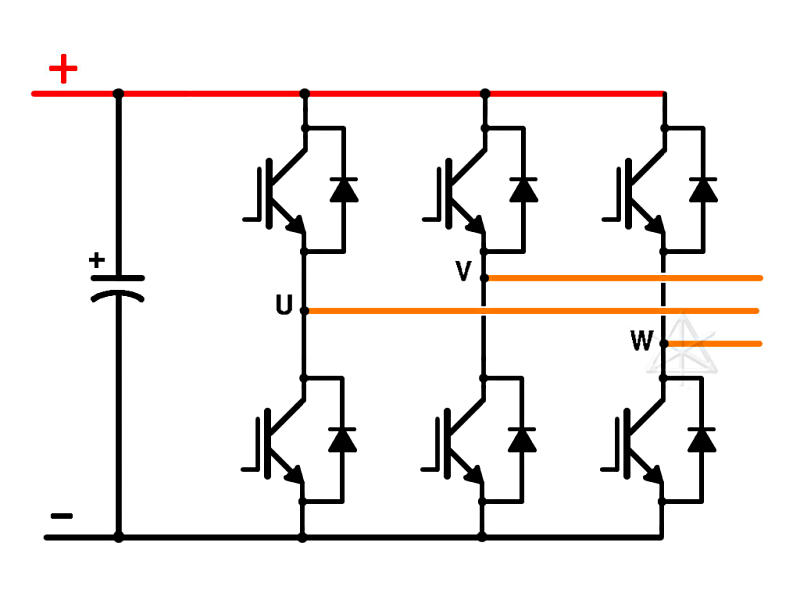
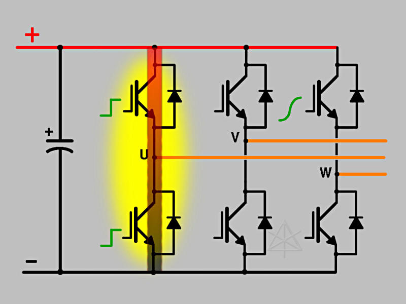
Common 3-phase inverter circuit
This shows up everywhere in hybrids and EVs
And even a few conventional vehicles now
Turns DC into AC for motor drive
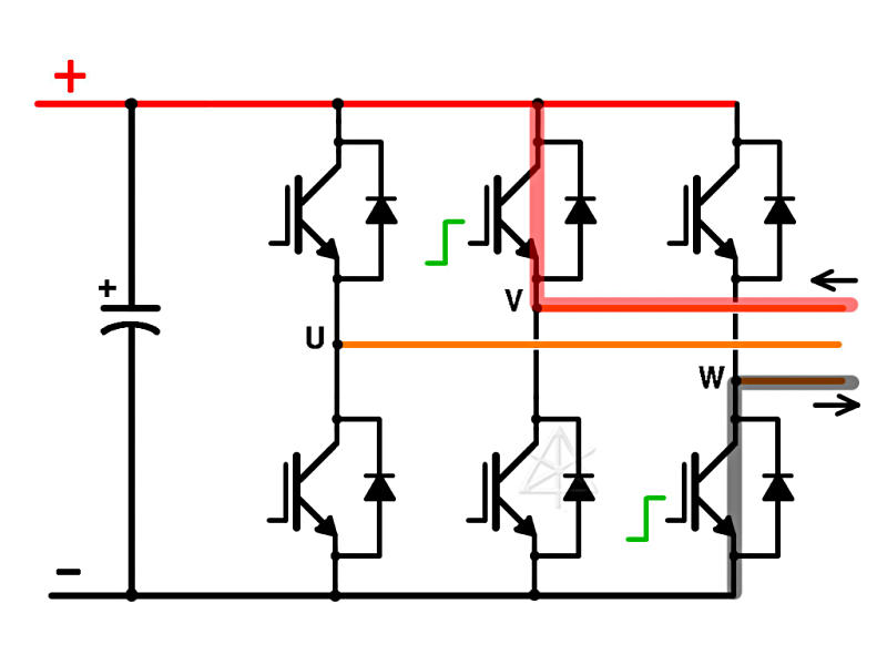
Controller turns on transistor bases
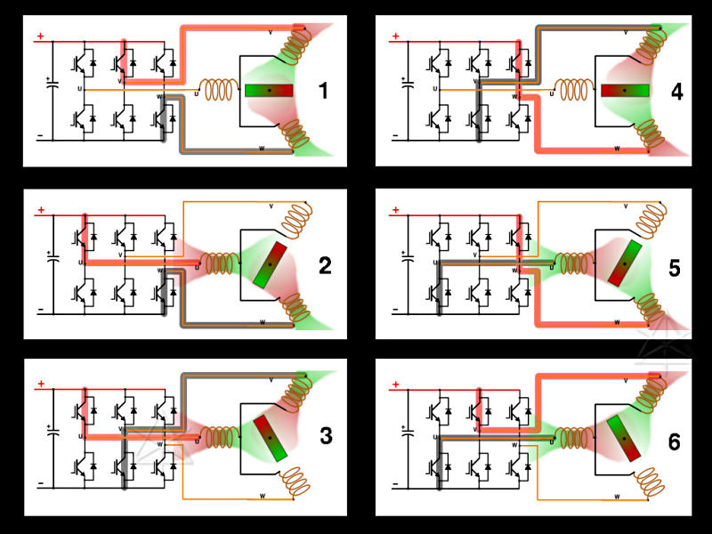
Six switching states
[Read down, not across!]
One changed connection per transition
To reverse, just swap any two leads
(or reverse commutation steps backward from step 4)
Motor controllers do this easily
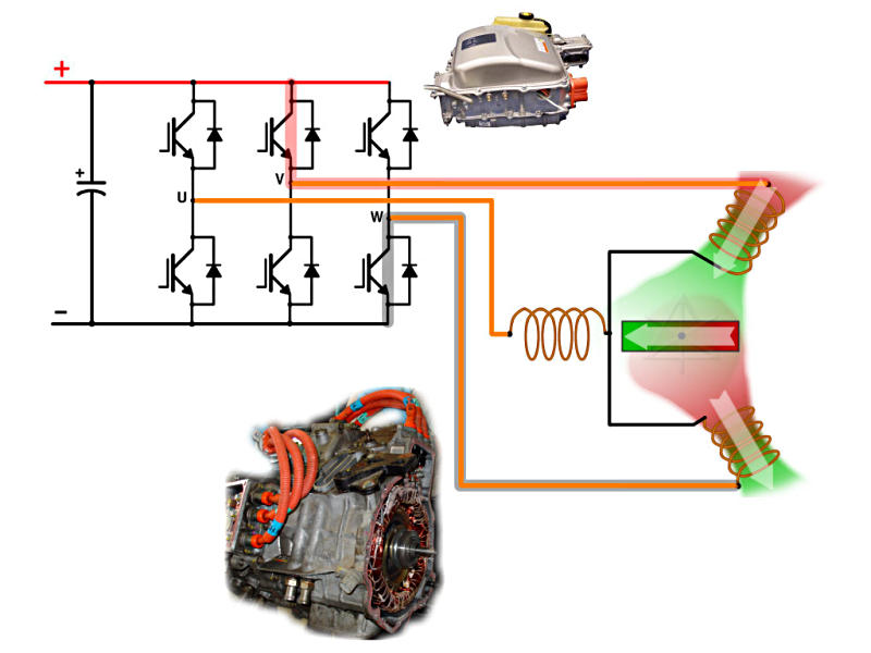
Modeling the car parts
Take away the transistors...
It all works in reverse, too
Spin the magnet, generate currents
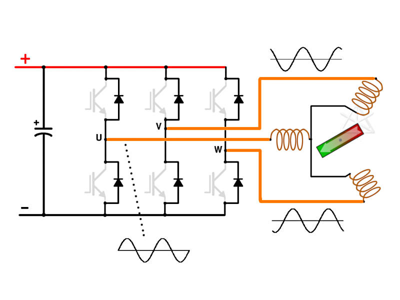
Typical 3-phase rectifying bridge
Almost every alternator contains this
Unregulated generating capability
No controllable field winding here
Magnets don't turn off
Don't dinghy-tow the car!
Switching both legs releases magic smoke
Need protective driver circuitry
Most inverters guard against this in hardware
Provision for minimum "dead time"
Halfway-on states are bad too
But what about sinewave drive?
How do we regulate motor power?
A method for current control
Resistors get HOT, right?
Transistors act like resistors if driven linearly
Partially on --> high voltage, high current, poof
All-on or all-off is more efficient
Off: no current --> low wattage
On: no (or little) voltage --> low wattage
On-time ratio yields average current
Switching rate is fast -- 10 or 20 KHz or more
Winding inductance smooths out pulses
Diodes smooth out turn-off spikes
Spike current sent into rails, helps charge cap back up
Helps avoid transistor breakdown
Variable duty cycle "fakes" a better sinewave
More poles for more torque, smoothness
Like two of our original motors in one housing
4 poles: 2 electrical revolutions / revolution
Coils could be series or parallel
Real-life cars ...
Insight: 12 poles, 6 r/r
Prius: 8 poles, 4 r/r
Civic: ??? Let's figure it out from RPM
Real-life motors are more "closed"
Few stray external magnetic fields
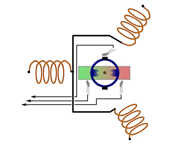
aka, "Where the heck are we"
No more mechanical brushes
We likely need some position feedback
Simple Hall-effect or inductive sensors
Small magnets attached to rotor shaft
Outputs trigger drive electronics
Frequently used in smaller motors, fans
And the Insight IMA ...
Reluctance-driven quadrature sensor
Tamagawa-Seiki "singlsyn" type
Two outputs change relative amplitude and phase
Faster and finer feedback than Hall switches
Used in the Prius
Referred to as the "resolver"
This explains the 6-wire position-sensor connectors
Driver/translator chips built into hybrid ECU
Completes feedback loop for electric drive
Armed with all this, class may continue...