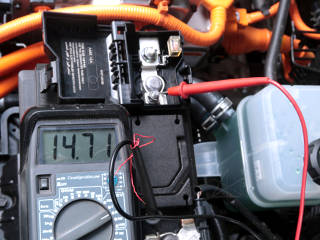
| The lovely big lithium battery is nothing without all the support electronics around it, and all of that runs on the standard 12-volt "auxiliary" system based around a traditional lead-acid car battery. This is an investigation into the 12V system characteristics in the Kona. |

|
It's worth knowing what the DC/DC down-converter for the 12V system produces, and when. I was surprised to see that its voltage usually runs rather high in the Kona on full power-up, where in the Prius it stays down around 13.8 or 14. Now, 14.7 volts or more really is too high to "float" a lead-acid battery long-term, even an AGM, and it wasn't like it had been dead and needed a high-rate charge or anything. At random times I saw it dip back down to a more reasonable 13.8, particularly while actually driving, but most of the time it seemed to stay up around 14.5 - 14.7. I asked a couple of dealer service guys about this; they had no idea if it was normal or not. I suggested to them that they might eventually see a lot of these cars come back with 12V batteries cooked dry by an over-enthusiastic low-voltage converter. |
| On a bit of further study, the circumstances around auxiliary voltage fluctuation get even weirder. I posted a more complete set of observations in a running thread over at InsideEVs, and still had no solid explanation why the level is all over the place until certain loads are turned on. The other folks who chimed in earlier seemed to think that 14.7 or higher was okay, so in this case maybe it's not worth worrying about too much. | |
All quiet on the idle front, eventually
|
I also did some quiescent-current measurements, because questions about
that always seem to come up.
A great example is seen in this
forum thread,
where there seems to be a lot of misunderstanding about the system and
the dubious "battery care" feature.
I posted some of my early discoveries into that thread, but here's the
more in-depth dump on what I could observe.
To simulate a fully everything-closed condition, I had to click the hood
latch closed with a screwdriver so I could leave the physical hood open
and still have direct access to the battery.
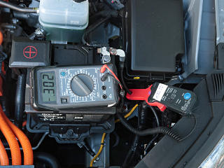
After powering the car down, various systems stay alive to do internal housekeeping and wait for any short-term events. This draws over 3 amps from the 12V battery for a while, which of course is now no longer being fed by the DC/DC. |
|
In a couple of minutes, that level drops to somewhere between 150 and 300
milliamps, which is still too much for a car just sitting parked.
This is somewhat variable, trending generally downward.
During this time, one can occasionally hear more relays turning off around
the car as their related control units finally decide to go to sleep.
After something like *20 minutes*, the current finally dropped to where the clamp-on couldn't accurately measure it anymore. A quick test with lifting the negative terminal off its post while bypassing the connection with a milliammeter showed the fully quiescent current down to 16 milliamps. That's acceptable, and a 40 or so amp-hour battery should be able to hold that up just fine for many days -- as long as you do *nothing* with the car. As soon as anything changes, like clicking the RKE or opening a door, all those standby systems power up again and the whole slow 3-amps-to-trickle dance happens over again. Turning off the memory-keepalive "fuse switch", visible at the very top of this shot, reduces base quiescent current to 5 milliamps. The car can easily be left "mothballed" in this state for a month or more, without the 12V going anywhere near flat. The only caveat is that the metal key needs to be used for initial re-entry, as the RKE and smartkey functions are essentially disabled in that mode. Turning this switch off seems to lose very little information, notably just some climate settings. Other stored information like driving modes, radio presets, charging schedules, etc -- settings we would *expect* to lose -- appear to be preserved regardless. Perhaps they're stored in some kind of flash RAM instead. One thing to note is a distinct possibility that "final" sleep current may occasionally be a bit more in other Konas due to their cellular modems still exchanging data to the BlueLink network. This may drain a battery faster, as noted later in that same forum thread, from someone who put his own BlueLink setup in a confused state. In *my* car the possibility for that has been permanently eliminated, by the means described in the "going dark" section. My reading was also taken without the "battery care" user option being enabled, which supposedly brings on the traction battery and DC/DC automatically once in a while to push a little maintenance charge into the 12V. But that's more electronics needing to stay powered and working to keep track of the 12V voltage, time, or whatever its criteria are, which may be more of the idle overhead it supposedly works against! There is evidence that the implementation of this in the Kona is fairly flawed and often results in a dead 12V battery anyway, so it doesn't seem worth using in the first place. I didn't bother to test this further; understanding the steady-state characteristics of my rock-bottom quiescent drain gave confidence that I could disable the "care" option and not worry about it too much. | |
LDC, OBD, m-o-u-s-e ...
|
Once the car is in full RUN mode with the main pack relays closed, the
12V system is kept alive by the low-voltage DC/DC converter or the "LDC"
as it's called here.
That's essentially the car's alternator, but like any other car with a
traction battery it comes from a downconverter in the power-electronics
block instead.
Early cars included simple hacks with an idiot-light and in some, an actual
ammeter, to show 12V charge or discharge and provide some warning to a driver
when the charging system wasn't working.
We can look at currents in battery wires all day, but that can't tell
us what the entire rest of the car is demanding in 12V power.
However, its own electronics can; we just have to know how to ask.
First, have another close look at this picture. That's not just an ordinary terminal-post clamp on the negative; it contains a very special piece of wire called a shunt. While it doesn't look particularly special, it is part of an intelligent battery sensor. The copper-colored strip of metal is a small calibrated resistance, which produces a voltage across itself in proportion to current flowing through it. About a millivolt per ten amps, it turns out, so it could indicate very high currents without getting particularly warm. The small 2-wire harness leading away toward the top of the picture brings current and voltage info back to the LDC, and thus the car can read the current into and out of the 12V system and keep track of its charge. There is a similar sensor, or possibly something like a Hall-effect device, for the LDC output itself. The thing to remember is that whenever the LDC is running and producing charge current, some of it goes to the battery and the rest goes directly to powering the car's systems. The difference between LDC current and battery current gives us the most true picture of the car's needs. Not only do we want that information, the car's own systems watch these measurements for control feedback. |
|
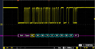
At some prompting from KiwiME on the forum, I fired up the DSO with bus-analysis enabled and observed that the little two-wire connection is indeed a data line, running a typical low-speed automotive protocol called LIN, or Local Interconnect Network. This runs at all of 19.2 Kbaud, but it's only sending one little chunk of data over and over out that little IBS connector, back to the a "sub battery sensor" input to the main inverter/LCD/everthing-else electronics block. A very temporary tap simply involved a thin sewing needle poked through the wire insulation long enough to capture a couple of packets, and then the slight injury taped back up afterward. Without a solid connection that I could let go of to go mess with other things, it didn't seem worth trying to reverse-engineer the packet contents. |
| The patents that Kiwi references in the forum thread hint at a rather excessively-engineered algorithm for trying to detect the state of charge of the 12V battery and micromanage it, very likely leading to all the wacky variations we see. It's also weird that the shunt part of the IBS is NOT shown in the schematics on the negative terminal, which is confusing. Whatever. We still get an accurate picture of what's happening right at the battery. | |
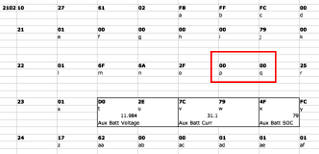
| There's a Github user called JejuSoul who participates in quite a bit of investigation into Hyundai and Kia automotive data networks. He/she[?] is referenced in several places in these pages, because with modern cars already being so self-instrumented these days it's often easier to just utilize data from existing sensors rather than installing our own. But the right information doesn't come easy, and is often missing or incorrect if the relevant research hasn't been done and publicized yet. A certain amount of reverse-engineering and guesswork is needed, to determine the right diagnostic PIDs to ask for and what to pick out of the answers. Jeju maintains an interim research spreadsheet showing various known or suspected parameters from OBD2 queries, and once we understand the general methodology for reverse-engineering these we can try to take the knowledge further. |
|
12V battery current from the negative-post sensor was more or less known about, although the math for the Kona turned out to be a little wrong. The figure for LDC current was already known or suspected for the Soul and e-Niro, the cars that Jeju and the community were most confident about to date, but seemed to not map over directly to the Kona. Due to how parameters are frequently grouped up in these data blocks, I suspected that the LDC info might be near the known battery info, and decided to explore some of the surrounding data. |
|
I kept some interim reporting going in an
InsideEVs thread,
and to summarize a long geeky afternoon's amusement, managed to get lucky
on another two bytes
in the block with high confidence of being the LDC output current.
By turning on a lot of heavy-power accessories -- headlights, rear defroster,
fan motors, butt-warmers, power windows, etc -- I could drive that figure up
to around 100 amps at times.
For the record, here's Torque-Pro CSV-format input for what I know about these two parameters as of this writing. I think I have the parameter order right. Any of these strings would have to be manually adapted to different OBD2 tools, which have different input formats, but the essentials include CAN ID, mode/PID, and the math to perform on the results.
What's super-weird about these parameters is the math for how the car reports them, particularly the battery current. First of all, the high/low bytes for both the battery and LDC currents are backwards from the typical order, evidently appearing as low,,high in the reply block. For the shunt sensor, this is visible by simply viewing the raw bytes and causing small current variations. Next, most two-byte OBD2 parameters are either signed or unsigned, and base from value 0. The shunt seems to map more closely to how typical sensor electronics compare readings to a "midpoint" reference voltage, with deviations above and below that representing the raw measurements. That's fine, we can understand 32768 as a "centerpoint" value and calculate relative to that, but what happens in the Kona is that the values come out in discrete chunky steps of the equivalent converted *decimal* value. Early experiments led to notes like "hmm, it's always X.68 amps, what's up with that" and another participant's high-resolution graphs clearly showed the values stair-stepping over time. Thus, the right answer seems to be to center around 32700, divide by 100 and accept one-amp resolution without any decimal fractions available. A different engineering group within Hyundai/Kia must have been working on this low-voltage stuff, without any standardized data model for encapsulating their OBD2 reporting. | |
|
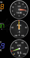
Regardless, the end result is a nice grouping of virtual gauges for the
12V system, as part of the developing "geeky dashboard" facility
[use big picture] for my
[hard-won!] OBD2 app.
The retrieved figures also correlate nicely with the "electronics" power
shown on the electricity-usage display on the center screen.
LDC current minus 12V battery charge current, times the running voltage,
gives about the right answer for the "blue number": overall 12V power
demand of the car itself.
The baseline shows very frugal power use by the essential electronics --
only about 150 watts total for the main display and the *forest* of ECUs.
It's never steady, though, no matter how it's displayed. The current draw keeps jumping all over the place by two or three amps, even with no changes in using the car's accessories. |
_H* 191001, 200205