|
As some of the earlier Priuses age, one problem that seems to surface fairly
frequently is failure of the little electric pump that circulates inverter
coolant. Keeping the big power transistors in the inverter properly cooled
is fairly important, and while the inverter itself can efficiently handle quite
a bit of power with minimal waste heating on its own, the coolant loop helps
ensure that any excess heat is taken out of the assembly fairly promptly.
As we saw hinted at in the teardown pages, there are thermal sensors embedded right into the power transistors themselves that can signal the hybrid ECU if things are getting too warm. But according to most owner experiences related on the forums, it seems that a dead coolant pump and lack of flow only becomes a problem on warm days and/or under high motor loads -- i.e. some drivers have likely run for quite some distance with a completely non-functional pump before the warning lights went on! And once the power handling capability is reduced after a thermal warning the whole unit can recover once cooled off and still limp the car along. So pump failure doesn't mean instantly being stranded by the side of the road needing a new inverter, in most cases. The pump also often gives quite a bit of advance warning that it's starting to go, by making somewhat different bearing noises as it's running. This seems to begin around the timeframe of somewhere over 100,000 miles, although mileage on the reported cases has varied quite a bit. Part of this is to describe why it takes that long and what to check for. As usual, smaller pictures link to larger versions for more detail. |
|
|
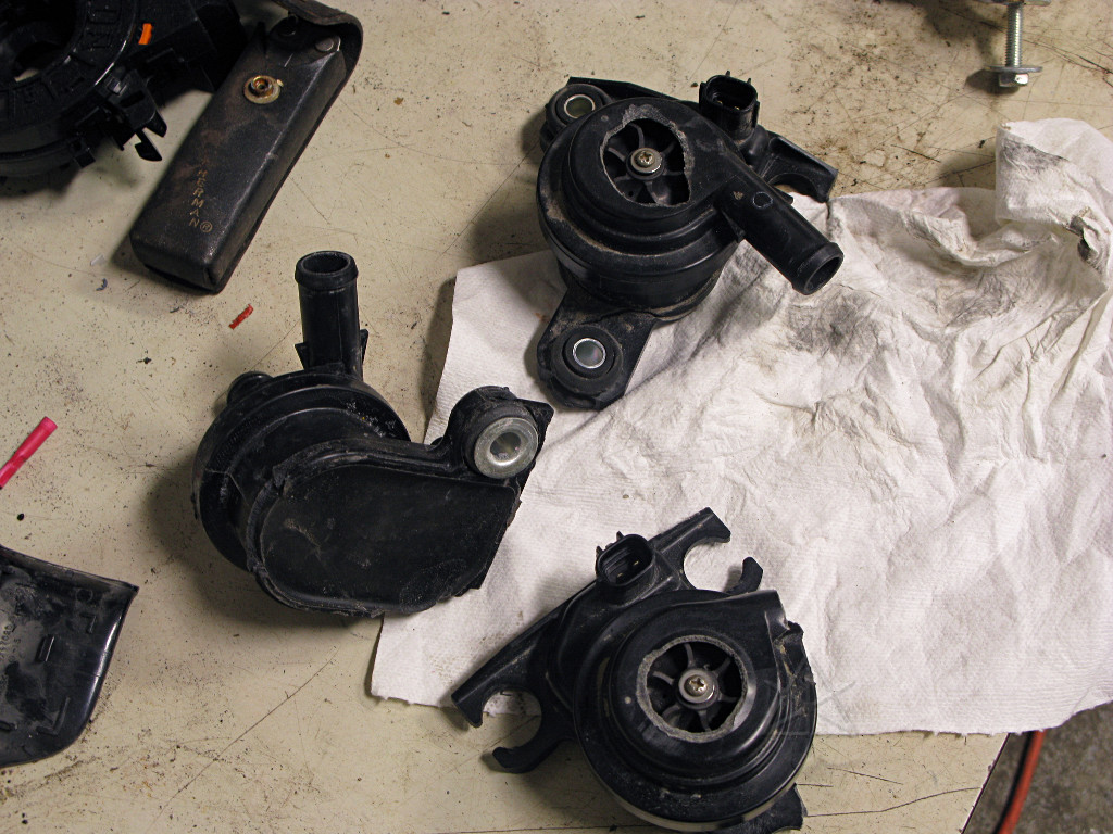
I had the good fortune to once again visit Steve at Autobeyours on the way home from Hybridfest/GreenDriveExpo '09 [pix link soon, hopefully] , and he has a large collection of unrecoverably broken pumps from all the front-end collision cars he brings in. He handed me a few, pointed at the tool tray, and said "have fun". I then attempted to find the correct way to disassemble them. |
|
There isn't one, really. It's a completely sealed-up unit, with the plastic
parts permanently glued together, designed to be an expendable replacement.
I finally resorted to simply hacksawing the housing in half to further reveal
the little impeller inside.
There are actually two impellers in this picture; one still in the unit and the other is an old one that Steve had stuck to a nearby steel cabinet by its own magnets. |
|
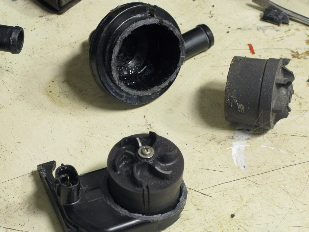
Removing the center screw allows the impeller and magnet-cup assembly to come off the shaft. Now we see where the drive coils are -- under a thin but completely sealed housing, which isolates the coolant passage from the electronics. The bearing shaft is hard-sealed into the top of that. The rotor cup has permanently-magnetized regions around its inside surface that are driven by the hidden coils. |
|
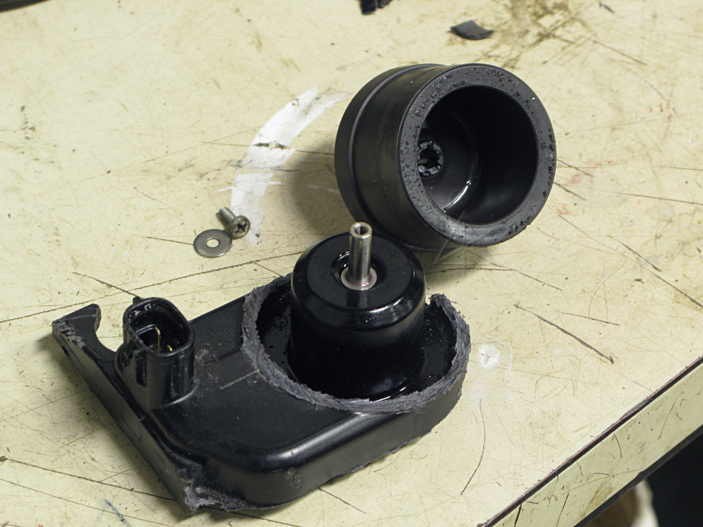
There's a fairly generous clearance between the rotor cup and the center pod
of the motor, so it's less likely that any small particles of stuff floating
around in the coolant would get in there and bind things up. But that's not
totally outside the realm of possibility. The coolant loop has no sort of
crud filter in it, so stray debris could show up anywhere. Keep things clean
when servicing!
[The scoring visible around the rotor here isn't from crud buildup, it's from the teeth of my hacksaw as it broke through the case wall.] |
|
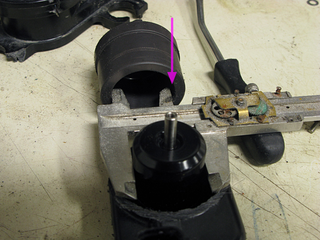
Here's the most likely problem and cause of eventual pump failure, though. In the red oval is the bearing area, where the rotor cup spins around the fixed center shaft. This isn't anything fancy, just a simple sleeve bearing which is immersed in coolant while running. Antifreeze probably isn't the best lubricant in the world, but more important is the fact that this bearing is only at one end of a relatively heavy rotor. Any imbalance in the magnet structure around the coil housing will cause significant radial stress on the bearing, which doesn't have a particularly tight tolerance in the first place -- there's quite a bit of play and rattle even in a *new* pump. It's sort of like the bearing is trying to control an umbrella in a windstorm, using only the flimsy handle! |
| It is fairly clear that Toyota quickly realized the problem too, and has improved the pump design for the 2010 Prius: |
|
|
The new design supports the rotor with bearings at two places -- a fairly
obvious fix for the vulnerability of the single bearing. It's always fun to
read these effective admissions of previous engineering corner-cutting in the
"new car features" descriptions of incrementally-improved models. But
sometimes it's hard to predict what will hold up and what won't, and Toyota
still gets plenty of credit for pinpointing and [eventually] dealing with
flaws.
The new pump system for 2010 can also run the motor at variable speeds, instead of the steady full-blast in the second-gen. There are five or six thermal sensors scattered all around the new inverter, and the hybrid ECU makes a decision how hard to run the pump based on their collective input. This undoubtedly saves pump wear. The older pumps run continuously all the time the car is powered up, even if only to IG-ON rather than READY. A car in fairly typical usage averages little more than 50 MPH all told and sometimes quite a bit lower for a city driver, thus by the time it reaches 100,000 miles it could rack up somwhere between 2000 and 3000 hours runtime on this pump depending on the average travel speed. 2000 hours is the typical TBO [time between overhauls] for most aircraft components, where too much time past that without inspection and/or maintenance is considered unsafe. Not that the inverter pump is necessarily a life-safety critical component, but it's interesting to note certain parallels in expected mechanical lifetime. I'm sure I've racked up my own share of extra hours on mine by sitting out at car shows and energy-fests all day with the system powered up so it can run an AC inverter and power some display stuff. |
|
The ironic thing is that the solution to excess runtime on *my* pump
was staring me in the face all along, and I didn't know until recently.
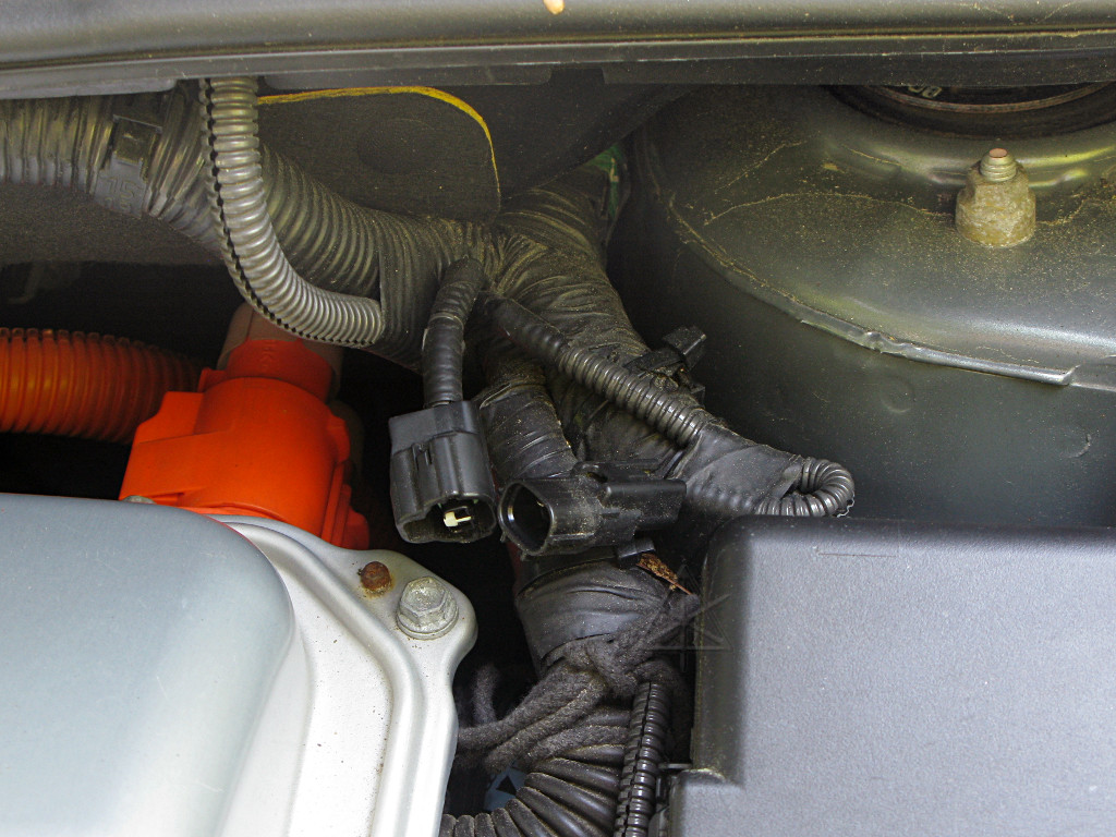
This is a shot of a rather mysterious connector in my '04 that is present in all the '04 thru '09 Priuses. It is a two-position connector, but only contains a single wire that jumps out of the harness, through the connector, and right back in again. Why? It turns out that this feeds power to the inverter pump, and the placement here near the harness-entry point on the inverter lends a strong suspicion that as the '04 Prius was being designed, Toyota was *considering* better thermal control based on inverter temps where the connector would instead feed through some sensing and control mechanism inside the inverter and let the pump slow down or turn off when not needed as much. But whatever it was going to be, it was never implemented for any of the second-gen model years. |
|
Regardless, this connector still allows rudimentary control for certain
circumstances. When the car is simply sitting powered up and just keeping the
hybrid battery and 12V system alive, even on a warmish day, the large metal
mass of the inverter box itself dissipates sufficient heat on its own that
the pump is simply not needed. Now that I can monitor inverter temps I know
this, and can simply disconnect this wire [much easier than trying to reach
down where the pump's connector is!] for extended times of sitting still.
That doesn't help the fact that at 110+ K miles as of this writing, my own pump is making rattly little hints that it's starting to go and will need to be swapped out soon. Eventually I expect there will be a page about that, but the Prius community pretty much already knows the drill with replacing these things and having to do the coolant-loop air bleed process fairly carefully. The thing is, the warning is easy to detect. Powering up the car to IG-ON in a quiet place allows a driver to hear the pump running even from inside the cabin, and a pump near end of life makes a distinctly different hum than a new one. Well, I notice stuff like that and establish a mental baseline of what's normal-sounding, which other people may not do so easily. Placing a hand down behind the left headlight to feel the pump assembly and hoses while it's running is also a useful diagnostic, as is watching for the little bit of pink turbulence at the back of the inverter coolant reservoir. [Update: my pump did get replaced not too long after the creation of this page, and was quite easy to do; details were simply worked into a section of the 100K maintenance page set. | |
|
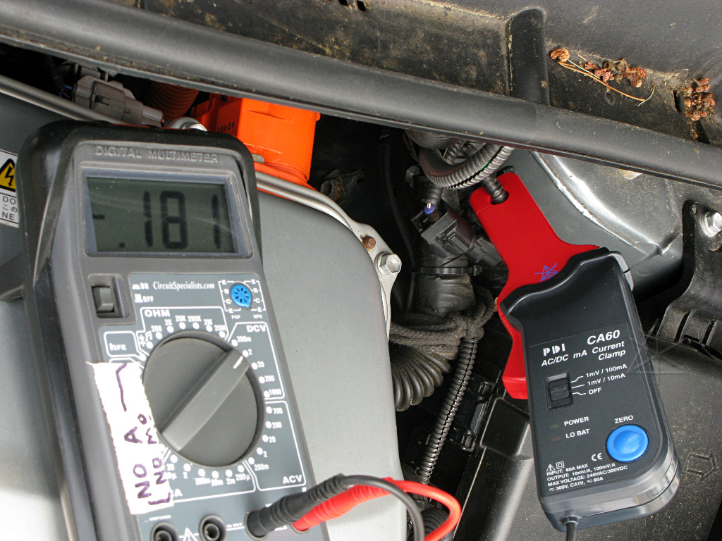
The mystery wire also provides a convenient point to measure current drawn by the pump when it's running -- about 1.8 amps, and possibly a tad more when the coolant is cold and more viscous. So disconnecting it reduces overall accessory draw by up to 25 watts. Over an 8-hour stretch at a show or other event, that's worth 4 of those little green 50-Wh car icons! |
|
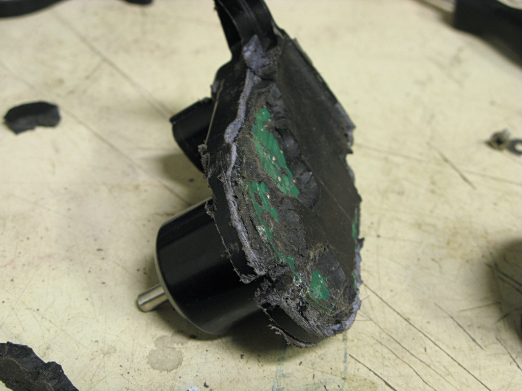
Some analysis of the little circuit board that drives the motor seemed to be in order, but as I continued semi-destructive disassembly it made itself really hard to get at. The whole thing is potted in some fairly tenacious rubbery goop. |

|
A bit of brute force and more hacksawing got it about half exposed, but obviously some parts have already been ripped away here and are still stuck in the potting compound. |

|
Finally I half-desoldered, half-tore the board away from the three leads
that go into the motor windings. A dubious victory here; enough was missing
or still buried to pretty much preclude analysis, and that *is* a bandaid on
my thumb. It is likely another little three-phase unit or similar brushless
setup, which would probably be extremely reliable if it wasn't for the
Achilles heel of that impeller bearing.
Steve looked at this and noted the strange little hockey-puck component near the power input leads which we both figured was a reverse protection diode, and he said "well, let's take the BIG power supply and find out!" The board didn't draw much current at all when the connector leads were powered in one direction, as it no longer had several key components and no motor to drive, but when we hooked it up in the other direction ... |

|
... the ammeter on the supply went WHAP against the right peg, and the diode passed ALL the current and got hot enough to melt itself right off the board. Presumably some ignition fuse would have popped long before that point if it was reverse-connected in a car! Many modern automotive modules have similar diodes for exactly that reason -- it's better to blow a small fuse on a connection screwup than reverse-bias and smoke all the important circuitry in an expensive unit. |
Inverter pump takes a dive
[fairly long-running]
Pat Wong's pump replacement rundown
[without pulling the headlight!]