
|
There have been
numerous methods
that Prius owners have used to run power inverters from their cars, often
to supply circuits in a home during outages. Part of the appeal is that
the car can stay powered up in a "standby" state for long periods of time
but use very little fuel, as the engine only runs once in a while to top
up the main battery when its charge drifts down to a low limit point. And
of course it is its own transport system for bringing power into a site,
the only disadvantage being that it has to disconnect from the load
for a while to go fetch more fuel.
Most of the systems tap into the 12-volt auxiliary system because there are many existing products designed for that, but relatively few of them are able to tie into the 220V "big battery". One or two schemes over the years involved custom rigs using commercial UPS systems or islandable photovoltaic inverters, but they were generally one-off hacks. For output any greater than about a kilowatt, the 12V system is inadequate as it can only supply an absolute maximum of 100 amps and you really wouldn't want to put that kind of sustained load on it. However, there's one small-volume product that the guy behind it calls the "plug-out" system, sort of a play on "plug-in" which was a different sort of effort to wall-charge the propulsion batteries in the car. It hooks into the main hybrid battery, and thus can provide considerably higher power output. Randy Bryan runs a supply line that he's named Converdant.biz, to import a particular line of inverter models from offshore and repackage them to be Prius-ready. These go up to as much as 5 KVA and the big difference is that they can produce 240/120V 60Hz split-phase power just like what comes into homes in the US. This allows running 240V appliances such as heat and well-water pumps, potentially a lifesaver in long winter power outages. Let it be clear up front that I had nothing to do with the design or supply of these things -- this is only to describe my particular testing and adaptation of one unit, which may help readers who are looking for similar systems themselves. The modifications done here are purely a matter of convenience, and as always, be careful when working around high voltage. |
|
|
I opted for the 3KVA unit, which actually supplies about 2400 watts once power factor and losses are accounted for. Randy was having sort of a special on those at the time, although in retrospect I sort of wish I'd gone for a larger-capacity model. It and all the ancillary parts came in a relatively featureless box, which nonetheless yielded the first hint as to offshore manufacture in the fact that it's made of that typical flimsy short-grain cardboard that's relatively easy to rip. |

|

|
|
What's inside, for starters, is ... a lot of air. The box is *huge* for
the amount of componentry it actually has to house. But it appears that
the same enclosure is used for all of the larger capacity units too, so
clearly a bigger output transformer and a different set of inverter
boards could fit in here. This setup weighs about 80-90 pounds.
The box and side panels are steel and the latches aren't very well designed, with a fair amount of rattly play when closed up. The control and inverter boards seem solid enough, with reasonable screw terminals soldered into generous land area for the larger wiring lugs to connect to. There are quite a few LED indicators scattered around inside which either blink patterns or stay steady-on and there's no documentation on what any of them mean. The front panel has a backlit LCD and a four-button menu system for configuration and monitoring, which powers up and reads "welcome to use the 220VDC inverter". No shit. The paper manual that comes with it is in similarly fractured english, as one might expect, but readable enough. While Randy's a little cagey about exactly where these come from or how they've been modified for this particular purpose, he makes no bones about the fact that they're 100% from China in both design and manufacture. My best guess is that they're some sort of PV inverters or the like that happen to have input voltage ranges suitable for use with the Prius battery. I'm sure Sunny Boy or Trace or Exeltech could come up with something equivalent in their sleep, perhaps in a more sensible form factor, and might even be price-competitive.
| |

It should also be noted that these units are completely *devoid* of any approval or conformity markings from UL, CSA, CE, ETL, FCC, or any other evaluative standards organization. Probably illegal for commercial sale in the US, in fact, but in this situation it's as though Randy was building these in his basement and selling them privately to owners who fully recognize what they're getting into. | |
|
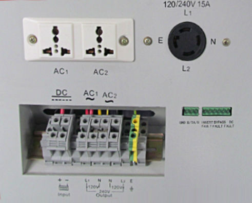
The rear panel originally looks like this:
[pic snarfed from the website] |
|
|
The white block on top with the oddly shaped holes is an "internationalized"
120V duplex outlet that can supposedly accept many different types of plugs,
but unfortunately it's a flimsy piece of garbage that is actually hazardous
and on top of that, it has the AC hot and neutral contacts reversed from
the standard BY DESIGN AND LABELING. The contact pieces inside it are so
convoluted and thin in their attempt to be in the right place for the
various plugs that they're not up to handling high steady-state currents,
and could easily get bent aside by an off-axis plug insertion. [I want
to say I'd be surprised if the Chinese actually *use* these themselves,
but electrical safety standards there aren't exactly in line with ours
in the first place.]
The little green pin block would presumably be to carry some sort of control leads and a serial link, except it isn't actually connected to anything inside. The manual has some superficial documentation about it having an RS232/RS485 link but doesn't describe any of the protocol it might use other than saying it "uses modbus". Here the block is basically just filling a hole, a vestige of some different configuration that was probably more toward the original purpose of these units. The L14-30 twistlock connector is okay, and provides the two legs of 240V plus neutral and ground. As it comes, neutral originates at the output transformer and is completely floating from chassis ground but can be bonded at the DIN rail terminal block, where all the connections for battery input and the AC output also appear. This allows for relatively easy hardwired connections, maybe, but I wasn't about to mess with screw terminals every time I wanted to hook this thing up and wanted a more elegant solution for bringing the battery in. | |

|
The Stupid Outlet got summarily diked out and replaced with a real spec-grade duplex, properly split into one outlet per leg and adapted into the case opening albeit in a slightly klunky way. Then I turned my attention to where and how to mount a good Anderson connector, and the semi-obvious place was to widen out that pin-block hole and mount the connector on a bracket just flush with the surface. Here it was conveniently close to the terminal block and could wire straight over to join in with the internal battery supply wires. |

|

|
|
I already had put in a connection to the battery in the car when I had its
box open a while back, described here,
so it was a simple matter of a short lead from it up to the Anderson and
then I could fire all this up and test it. The on/off switch is the fifth
button under the display which needs to be held down for a second or three
to make work, but then the unit comes on and produces quite a clean sine
wave. It's almost completely silent, only the faintest hint of 60Hz buzz
from the innards.
Important note: It is advisable to tie the AC neutral and the green/white chassis ground points together at the terminal block, creating a common ground for the output circuitry and the surrounding box. The right-hand picture above shows the easiest way to do that. This eliminates some 5 and 10 KHz hash artifacts that otherwise show up on the output, which I believe come from the Prius itself via the DC connections and have to do with the car's own ground-leakage detection system. The battery and primary-drive subsystem *should* be fully isolated from the output, but there's a little bit of high-frequency coupling that apparently tries to sneak through the plug-out circuitry via the floating chassis. See more waveforms for a deeper exploration. Bonding the chassis and transfomer grounds together suppresses the garbage. I tested with loads of different reactivity characteristics -- a space heater for resistive, a window-fan for inductive. The output waveform remained pretty clean and stable under most of this, only flattening a tiny bit at the top and getting a little wiggly at zero-crossings under the highest loads applied but holding up quite well. No big phase shifts or anything at abrupt load transitions. The car never complained about the parasitic battery drain -- this all hooks downstream of its current-sensor "donut", so the car knows all about the fact that battery current is going *somewhere*. It has to, if it's going to manage its pack charge correctly. The output limit seems to be a little north of 10 amps per leg, and that's on *either* leg rather than an aggregate power limit out -- meaning that a 120V load can't receive more than about 1200-1300 watts without the inverter going into overload. It'll handle *two* such loads just fine as long as any of the currents don't go much above 10 amps, but that is arguably a deficiency that makes its "3 KVA" rating a bit misleading. When the inverter goes into mild overload it simply shuts off the output for a few seconds, and then brings it back on for a while, shuts off, comes back on, etc. In a higher overload state it simply shuts down and needs manual intervention. The fan runs if the heatsink becomes too warm, whereupon a thermal "clicker" simply enables it. It blows inward toward the general direction of the inverter board, as there really isn't a specifically designed air path through the rest of the box. Almost like it was an afterthought. | |

|
With a high load on one side there's a bit of odd hash on the neutral line, but nothing major. The inverter's display always shows some token amount of nonzero neutral current even with no load connected; not entirely clear why but it may be able to be calibrated away. The unit has various compensation settings for its own internal measurements, which can and should be fiddled with to bring currents to zero under no load and voltages in keeping with reality. See this rundown from a collaborator for more info. |

|
An IR shot of the guts after all the testing showed the transformer and
inverter heatsink fairly warm, but nothing unexpected. This is another
hint that higher capacity units might have beefier parts in these places.
The unit actually dissipates very little excess heat in operation, so
its efficiency is up to present expectations.
[Snark: so clearly, intellectual property was stolen from the right places.] |
|
So that was the early round of testing; other than the somewhat disappointing
load limits I didn't see any issues with the thing, and to bring power to
somewhere was a simple plug-n-chug. Abrupt connection of capacitive AC
loads like switching power supplies with poor inrush limiting may cause brief
overloads, but that can be worked around by switching them on before turning
on the inverter.
To be safest, one would reasonably assume that the input hookup should be connected before firing up the Prius. But the unit does have its own "precharge" system through a 200-ohm resistor, so it actually can safely be "hot-plugged" with the car already powered up and it won't spike the hybrid battery. A relay clicks over to bypass that once the internal caps are up to a nominal voltage level. I had to fiddle with the low-voltage limit, because when the car is sitting idle it tends to run the battery charge fairly low before topping it up. This gets down around 200 volts and then when the car goes to start the engine, the current surge to the motors dips it down closer to 195. The inverter's limit seemed to be about that and this was triggering error conditions, but fortunately that limit is user-configurable and pushing it down to 190 seemed to be sufficient. The Prius battery voltage varies over quite a wide range in normal operation, but we knew that already. One nice characteristic is that the output *is* fully transformer-isolated from the car's system, which is important because if there's any ground fault or cross-leakage from the hybrid system to the car chassis it will light the "ZOMFG horrendous error" triangle of doom and shut down. With the option [or mandatory practice, as I regard it] of bonding the output neutral to the inverter chassis and thence to the car *and* the earth, I can turn it into a proper "separately derived" safety-ground-referenced power source without putting the hybrid system or people at risk. |

|
From there it was a matter of taking my new toy on the road to supply power at various events that I specifically had in mind when buying the thing. One is three days of powering a bunch of lights in an otherwise completely dark parking area at a woodland retreat, shown here; the car was its power source and also my little sleeping nest. The inverter helped keep things cozily warm on the overnights but not excessively hot; most of the heat inside the car came from the exhaust passing underneath anyway. The tarp stretched over it allowed leaving my windows open with bug-screen over them and no worries about rain. |
Part two

|
Finally, about a year and a half later, I decided to test it on the heat
pump. Part of the holdup was building an appropriate pass-through
penetration for the basement wall, because part of the idea is that if
this has to be done in winter then where the power comes in has to be
kept airtight. I dug out a suitable cable and put on a twistlock plug.
This basically shows where I put the inverter when it's in -- the hatch
can just close over it, and there's room for my sleeping berth next to it.
The little casters on the bottom of the box had long since been removed.
Some people prefer putting the inverter near the load and running the DC battery leads the distance over to it; I like keeping all the works local and running standard extension cords out to where they need to go. |

|
One mild concern about the Daikin heat pump was its current-draw characteristics. It's an inverter-drive compressor on its own and is completely soft-start under all conditions, but I had already seen that its *current* waveform is pretty ugly under steady-state running. This shot is from the house-renovation studies, with a current clamp around one of the leads to the outdoor condenser unit. What would this oddball reactivity do to the inverter's sometimes overly-sensitive current monitoring? |

|
So I brought in my wire and backfed it into the HVAC panel through a
breaker swapped in for the feed to the resistance-heater which is usually
not even installed in the air handler anyway, and let 'er rip on an air
conditioning test as it was still summer. This would at least tell me
whether or not this lashup could run the compressor and all the other
associated equipment at all.
It did, and evidently quite handily. Less than 4 amps per leg shown on the inverter's display, about 5 amps from the car's battery, and no complaints. This would go up closer to 7-8 amps in full heat mode, but likely nothing the unit couldn't handle. Okay, big test finally done. Kind of odd to know the Daikin was running without seeing the meter disk spin. My "transfer switch" to avoid backfeeding the utility is to keep the 60A subpanel breaker in the main panel turned off. In real power-outage conditions I could run smaller 120V loads like lights and the fridge from a couple of outlets on the HVAC panel and some extension cords slung through the house. |

|
So on a winter night after that horrendous infrastructure-smashing ice
storm I could see the place looking like this, with the car snugged up
against the house but the exhaust pointing away from it, and my little
umbilical going in through its air-sealed hole to keep it cozy inside.
With the hatch closed and more snow on everything, of course. The hatch
down just one click keeps weather out but leaves enough of a gap
underneath to not pinch any wires passing through.
If there are further notable adventures in this particular area at some point, they will likely be related here. |