Prius body ECU disassembly
This describes a somewhat surprising journey inside that white chunk of plastic mounted up under the left side of the dash. It was motivated by desire to find the right interconnects and hack up a way to enable the power windows without having to go to IG-ON, and also to allow the remote unlock fob to still work with the car powered up. Both functions are managed by the body ECU, and many of its interconnects are completely internal to the connector block it's buried inside. There's nothing particularly useful in the service manuals about it. Thus, exploration is clearly needed.WARNING: disconnecting wires in this area is likely to have the same effect as disconnecting the 12V aux battery -- settings such as radio stations, clock time, beep enable/disable, power-window calibration all get un-set and you have to put them all back the way you wanted afterward.
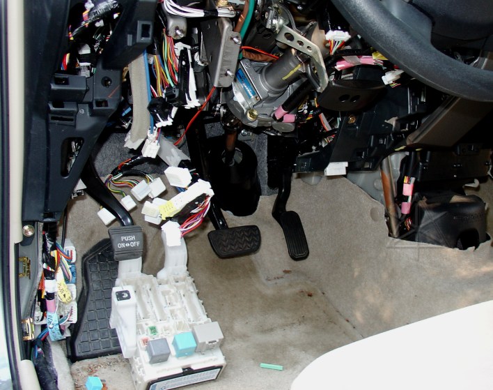
The "Driver side junction block", as it's called, mounts to the dashboard strut and the side frame piece with three bolts. The harder part is undoing all 18 connectors from it. Connector 1E, in particular, has a little green bar of plastic run through near its upper end which cannot be backed out until the whole J/B is moved away from a nearby metal brace. [The plastic bar is on the floor just ahead of the seat.] Eventually the block can be extracted, bringing the whole fuse block and three large relays down with it.
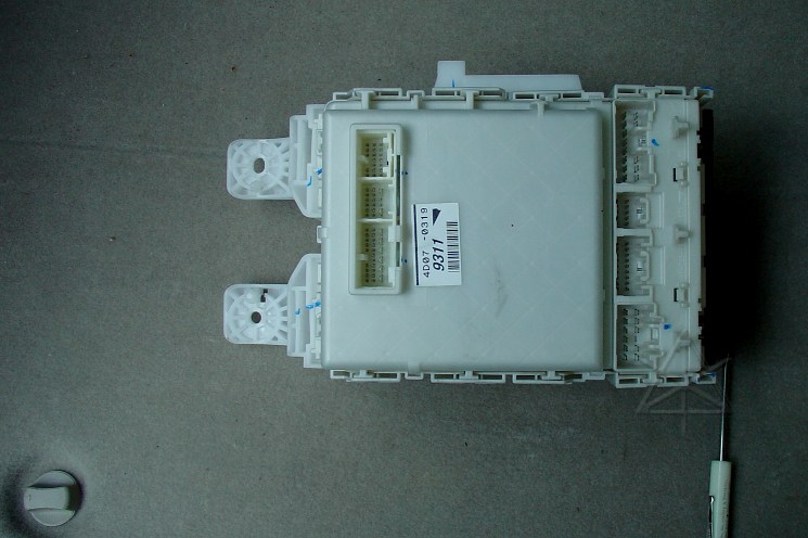
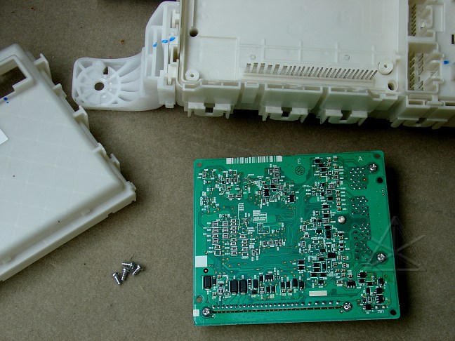
Now that the damn thing is finally out of there, we bring it around back for clearer workspace. This is the side away from the driver. There are four or five fairly obvious pry points to release the plastic cover. These should be brought out evenly, without tilting the cover too much.
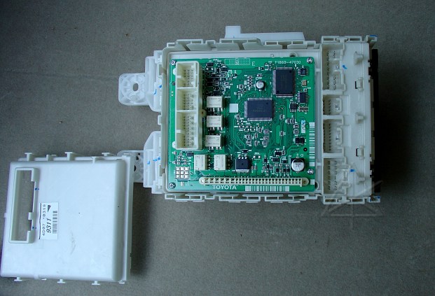
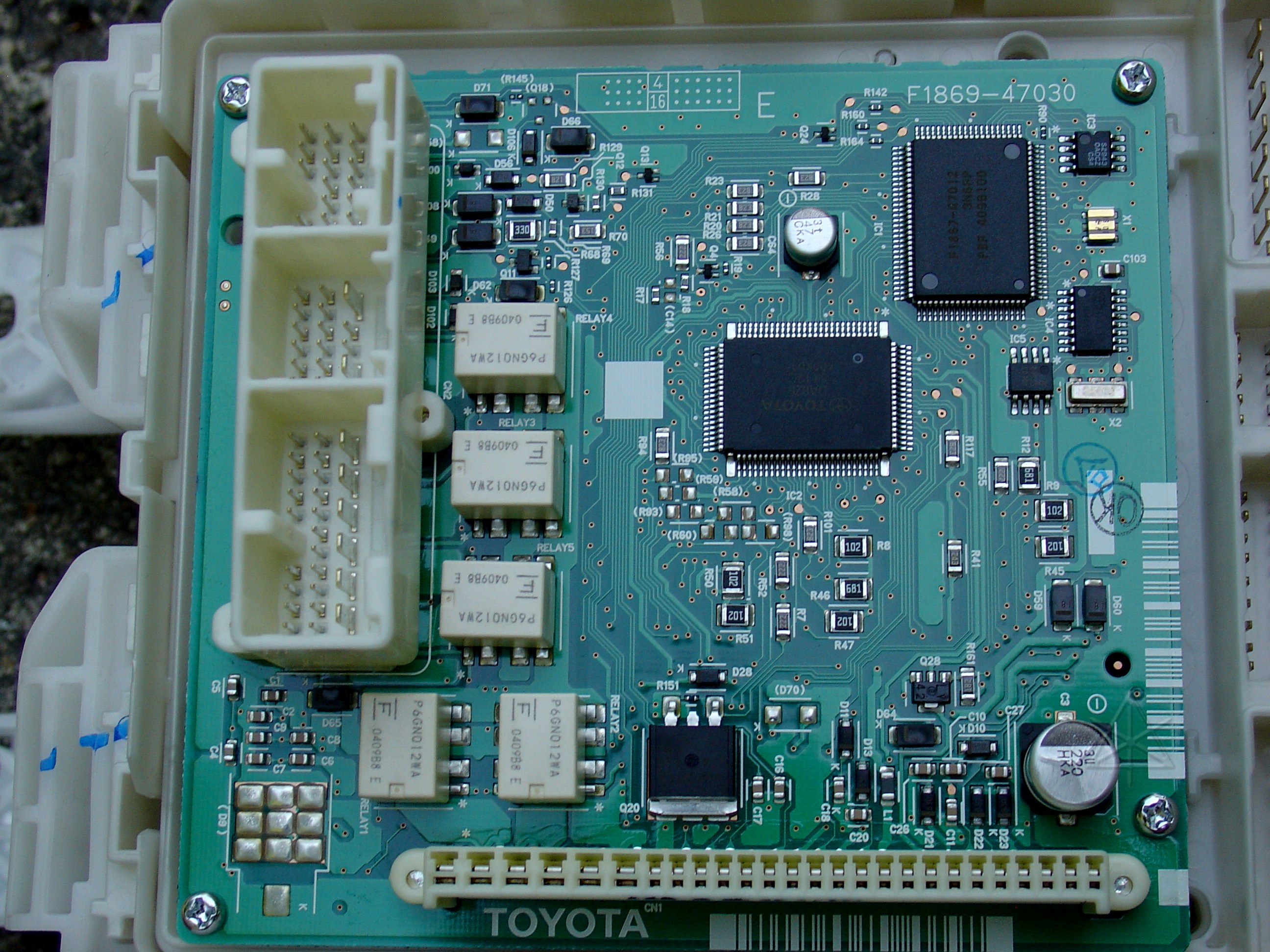
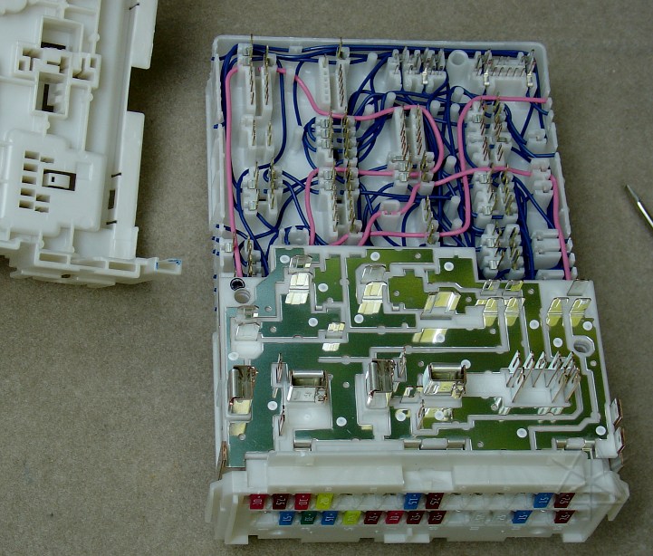
Aha! Here's the body ECU. The three external connectors [B5, B6, B7] are mounted directly on the circuit board, and the long thin one is the internal connection [unlabeled] directly into the J/B. Here is a detailed closeup of the board. [huge!]
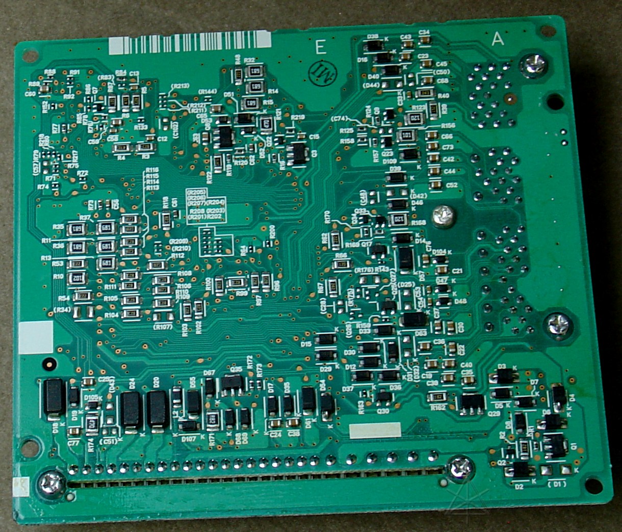
Removing four screws allow us to pull the board off its internal connector pins and view the back side. Here is a closeup of this side. [big!]
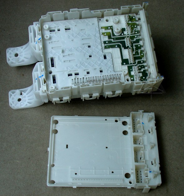
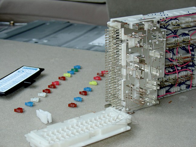
But we're not done -- this thing keeps going and going, like an onion. The next layer of plastic turns out to *BE* the connector housing, and can be extracted fairly easily -- leaving all its pins behind. They all just slip down through the holes. We're VERY careful not to bend them, or realigning all this will be difficult!
Next, after removing the relays and fuses on the front, the entire block of connections can be pulled out of the shell -- again, bringing all the pins with it. Talk about a custom molding job... It is immediately obvious that the connector block is composed of two layers, which appear to be trying to separate a little bit.
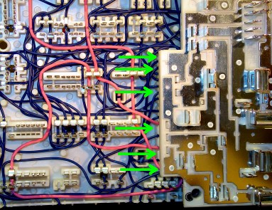
This is the really scary part: most of the interconnects between pins are done with INSULATION DISPLACEMENT connectors and solid wire. This is really surprising given the vibration potential of the surrounding environment and some of the heavyish currents running through these connections. At least the really high-current stuff lower down is done in one-piece stampings that are in little danger of coming apart.
Here's the closeup of the IDC swamp. [sizeable!] It is interesting that the wire ends are also run to slits in the plastic edge of the block -- extra anchor points. Likely that the entire thing is produced by machine, rather than human hands.

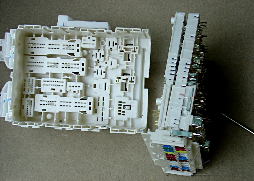
The halves won't separate until the fuse block part is removed. Which requires pulling all the fuses, and making sure the legend on the cover matches what we find...
after which the fuse holder shell drops off, leaving all the contacts. Now we can really see the bus structure for the fuse tree, as documented in the "power source" section of the EWD. The feeders are spot-welded to some of the high-power buses on the front of the unit.
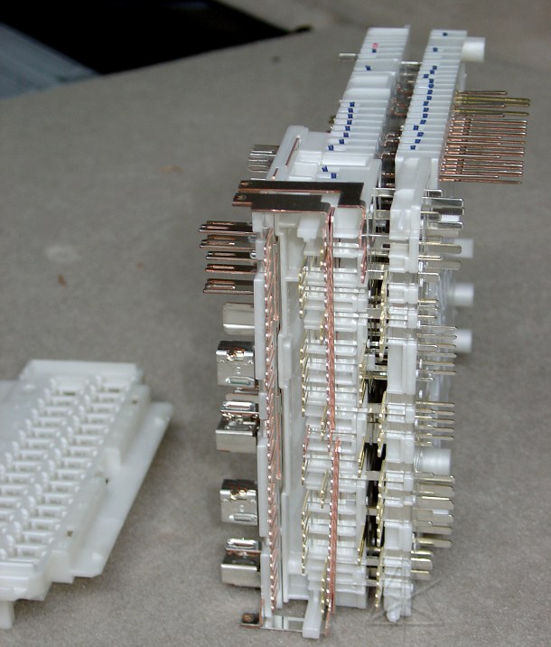
Another attempt to separate the halves is stymied by the fact that some of the fuse connectors attached to one half run underneath, and interfere with, connectors from the other half. At this point it looks like one would have to bend or break the spot welds to continue, so this is where it stops for the moment. Note, however, the height difference between various sets of pins -- some are attached to one half, and some to the other, and everything evens up when the halves are put together.
It almost felt like the bus-bar section wanted to separate away from the rest at this area, but it was impossible to tell if that would begin pulling some of the wires out of the IDC connections. I didn't risk it. However, having the unit this far apart did allow tracing some of the internal connections and determining [by powering them and hearing the click] that some relays really are embedded deep inside this thing, under the bus-bar panel. I couldn't even wedge things apart far enough to *see* them. This implies very difficult serviceability if, for example, the "PWR" relay for the power windows goes bad ... but of course Toyota's answer is "Replace body ECU" and gouge the customer for four digits.
It's all installed back in the car again by now, without any problems. Initial debugging results for the intended hacks are less than stellar. Enabling the power-windows relay via the 45-second-delay "KOF" line at ECU internal connector pin 13 lets all windows EXCEPT the driver's work, which isn't entirely useful. And from what I can determine the RF fob receiver always receives data and sends it to the ECU, but when the ECU is powered up in IG-ON or READY it completely ignores the data. In general the architecture around the body ECU lets it retain way too much control over the functionality, but perhaps that is deliberate since it *is* also a security component.
_H* 050913