New button, same old bullies

  As driver attitudes on the roads have continued to degenerate across the land, being able to control vehicle spacing in the rearward direction has become even more essential.  I described the original Yuppie Button and the motivation behind it as it was installed in the Prius, and with a decade-plus of experience behind that one I now view it as a mandatory safety feature for any car I own.  I clearly needed the equivalent in the Kona basically the minute I pulled out of the dealer lot, so getting one designed and put in was a high priority.

Unfortunately, it isn't feasible to design a universal "yuppie button kit" for any car.  Every vehicle's wiring system is different enough that it has to be a custom job, built with intimate knowledge of its base wiring.  The technology of how automotive lights are switched and driven, and even the lighting units themselves, keeps changing, so the right way to work with all that has to adapt as well.


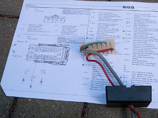
Design and build of yuppie button, on connector diagram With the schematics and more importantly the relevant connector information in hand, it turned out that the design for this car would actually be fairly easy.  Lights in the Kona are powered in a quite independent way, i.e. things like the front and rear directionals are not ganged together -- there are four separate driving circuits, one for each corner's lamp.  Even the brake lights are separately switched -- left, right, and high center, with three separate harness wires going back.  The immediate thought was thus a "diode spider", with a single switched power source splitting out to all the relevant lighting lines but not allowing any of them to back-power the others.

Intelligent power switch architecture There's another caveat, however: many of the auxiliary passive devices in the car are driven by what Hyundai calls "intelligent power switches".  These are not relays, they're basically power transistors or MOSFETs or the like switching positive battery power to whatever the load is, with some added smarts about current sensing and limiting.  And with all such solid-state switching devices, there's always a strong possibility that it includes a reverse diode across itself, either intrinsic in the body or explicitly added.  Thus, unsolicited power sent to an output, even through another diode, could easily wind up back-powering the supply rail for the IPS.  A test as shown here, with the load disconnected and the *positive* of the diode-check ohmmeter on that output testing back to the supply rail, indeed shows about a half-volt drop -- certainly not open.  Conclusion: the IPS elements do include back-diodes, and I would need to be careful to bring my button power *only* from a source that is hot when the car is fully powered up and all supply points upstream of the lighting are live anyway.

Yuppie-button diodes in compact box I did find a relatively convenient "only when ON" source capable of supplying enough current, from a wire fused at 25A that feeds power to the wiper motor.  The early button prototype with the diodes hanging in space was sufficient proof of concept, so the "controller" for this build would be a simple rack of old 3-amp 1N5401 diodes fed from my common source and sent to a handful of specific light outputs.  It could all tuck into a compact little box, and all of this was scrounged out of the "parts hoard" in the shop with nothing extra to buy.  I only had six outputs to feed, but with the reverse lights as the only ones ganged on a single harness lead, I doubled up the diodes and wires to that output.

Worst-case total current, with traditional 20-watt bulbs still in the reverse and directional lights, was going to be about 10 amps.  I intended to change the reverse bulbs out to nice bright LEDs anyway, so that could help a little.  Kind of strange that a 2019 model car still used traditional lamps at all, really.


Wires slit and exposed, ready to receive taps Most of the taps would be in the bundle from this one connector, making it pretty convenient to work on.  It's hard to see the exposed copper, but each relevant wire's insulation got a careful longitudinal slit and peeled back, so it didn't even get fully cut behind where the tap would get soldered on.  I fished the diode-box output cable neatly behind everything along the same path as the car's harnesses, and even found a use for some of the stupid black velcro cable-ties which I hate but stlll had kicking around.  For a permanent installation like this they'd be fine, and even matched all the fuzzy black harness jackets rather nicely.  It's some kind of foam tape, with a soft feel to it.

Tap connections done and taped up The connection task was straightforward, and each splice point got a little wad of gaff tape around it.  To avoid bulk in only one place, I staggered the positioning.  The Button and its wiring can also be seen here; with the kick panel moved back into place, the switch and wiring would tuck neatly in just above the big floor-level inter-harness connectors and have plenty of room behind with no metal parts nearby.  The switch is a heavyish-duty momentary, and directly handles all of the output load without any relays needed.

Yuppie button wiring done With everything back in place, it's hard to tell that anything changed.  I chose a "side-kick" button position mostly because the dead-pedal isn't really a structure; it's just a thickened and rubberized part of the carpet which sits over a pad and a metal bracket that's part of the car body.  Thus, there's nothing convenient to drill a button-mount hole through in the normal "stomp on it" axis.  That was okay; I'd keep it this way and build some kind of right-angle bracket later if I decided I didn't like it.  It's slightly more klunky to operate but not at all unreasonable.

Yuppie button controller tucked up, pilot line tap The diode box got tucked up behind another module next to the firewall, tied up with a bit of trickline and stabilized with tape later.  Almost completely out of sight, and it almost looks like an original part of the car except for the stray bits of gaff tape.  There's actually a ton of room under the dash in general, with things not quite as crammed in under here as with the Prius.
That box whose bracket I used as a support is interesting in its own right.  It is the Charge Control Module, which only comes into play during high-speed DC charging.  Even though it's completely out of harm's way under the dash here, it has a big fancy weatherproofed connector, and appears designed for under-hood mounting instead.  The parts-location picture for it is also a very different style than the other photos in the same section.  This strongly implies that an original design called for it to be under the hood near the charge port, but got moved here later using the same hardware.  Perhaps other car models have the same thing under-hood, dunno.

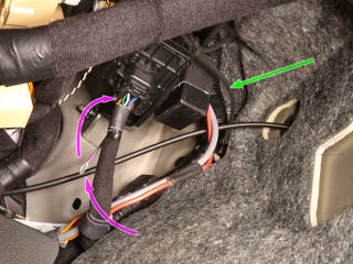
What having the CCM's harness here does provide is an accessible tap of the charge-port pilot line, which is otherwise buried in heavily weatherproofed harnesses running straight from the charge port to the on-board charger.  I would certainly want to watch this line during DC fast charging, because it's where all the magic happens as far as communication between the charger and the car.  So while working under here I added a short tap wire to the pilot line [pink arrows], which in the CCM's harness is the white wire.  It could just hang here quite safely, and would be easy to hook a scope probe onto.

The separate charge-control module and evident indecision over where to mount it isn't the only thing that makes me think that fast-charging capability may have been kind of a last-minute add-on to the Kona design.  I discuss that more in the rapid DC section, where I finally get around to testing that.


Comparing reverse-light bulbs I ordered some "super bright" LED bulbs for the reverse lights; here are various types I could play with.  The original bulbs and shorter LED ones are all kind of "meh", but the big corncob on the right is significantly punchier.  A minor downside of that type is that they're marketed as "canbus error free", which simply means that they have load resistors inside to make them look like regular bulb loads to things like flasher relays and dead-lamp detection circuitry.  [Except that these are white, and less likely to be used as directionals, so why bother?]  Because of that they draw almost as much as the stock incandescent bulbs, so I was still glad of having doubled up on the parts feeding the reverse line.

  [ Up to EV index ]

_H*   191014