and a couple of preliminary electrical observations
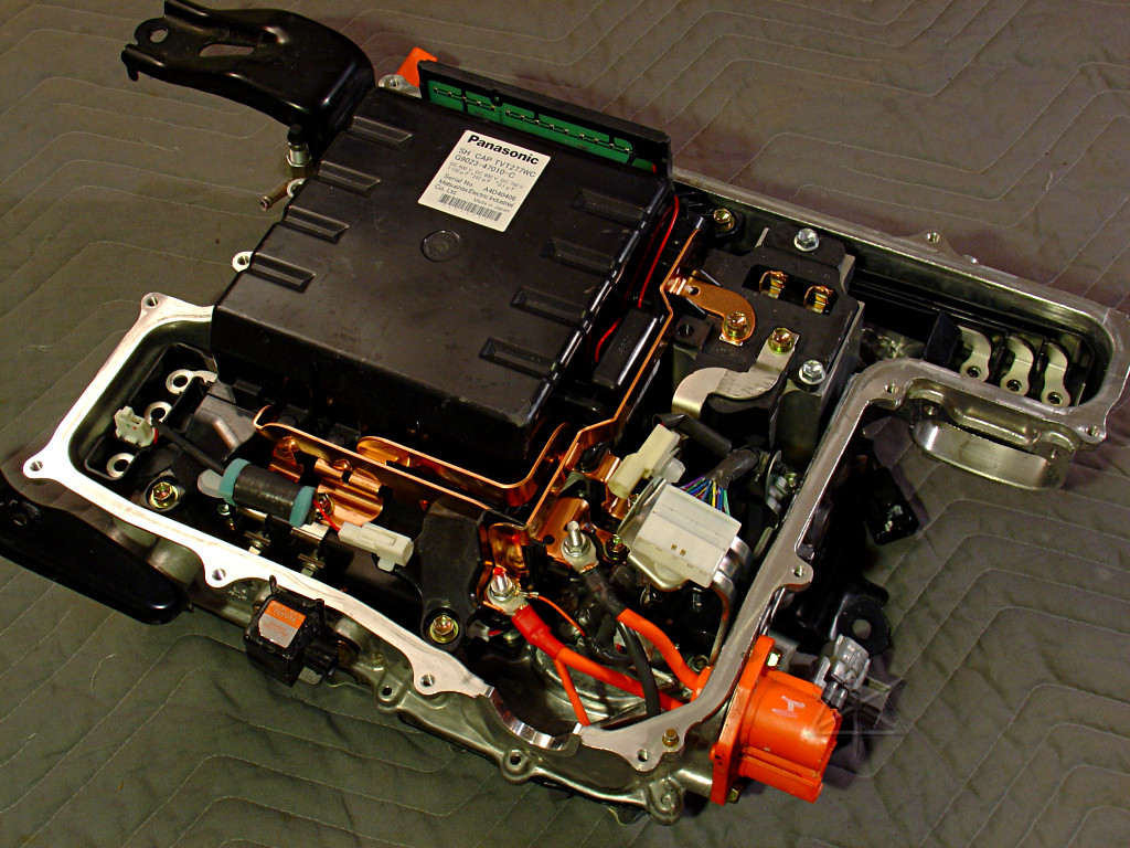
Now that the main unit is superficially cleaned off, the next step is to
dig farther in, find any further damage, and document how it's put together.
A nice perk is having some additional and more or less expendable modules to
compare against and partially destroy, if necessary, in the name of science:

	power IGBT rack
	boost inductor
	boost driver
	DC/DC and A/C board
	capacitor block

Again, use the linked large pictures for clarity.  Really.
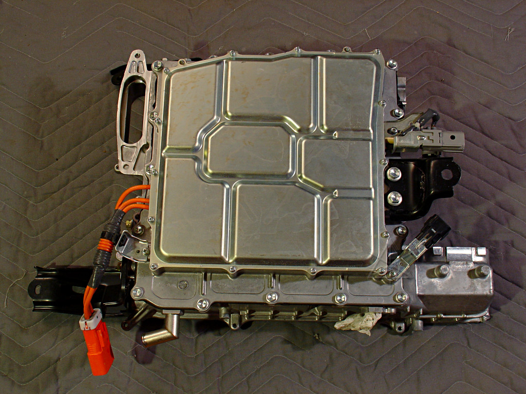
The HV battery hookup is one of the few places in the Prius that actually use
black for negative and red for positive, even if just in a token way on the
lug sleeves -- except that it's 200 volts, not 12!  [Everything else around
the car's wiring is an insane mishmash of colors, with black frequently used
for +12 and white/black-stripe for ground...]  Here the battery leads come in
through a weathertight fitting and just connect straight to two of the bus
bars.  Additional taps on the same posts carry the battery supply down through
the body of the inverter to the lower half.

This is why it's important to wait a while after disconnecting the battery
before messing around in here -- the relays and service plug are in the back,
but the capacitors are still connected up front and until they discharge,
can easily continue to backpower the whole HV system all the way into the
battery box.
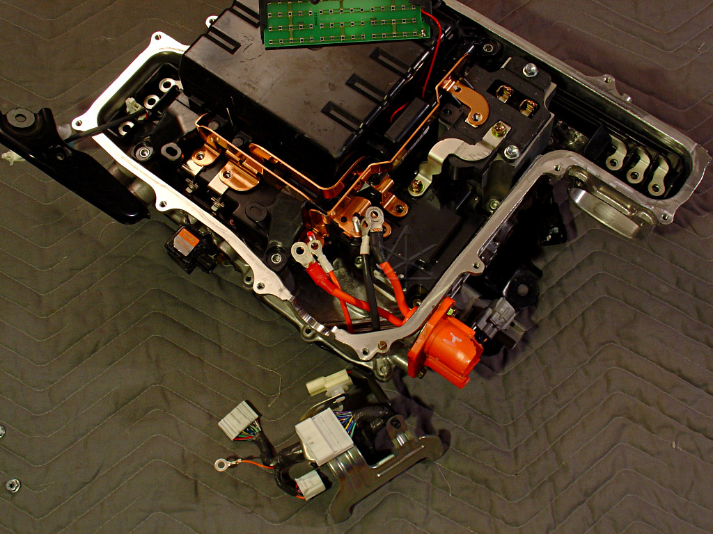
The little internal control harness removed, and various things starting to
get disconnected.
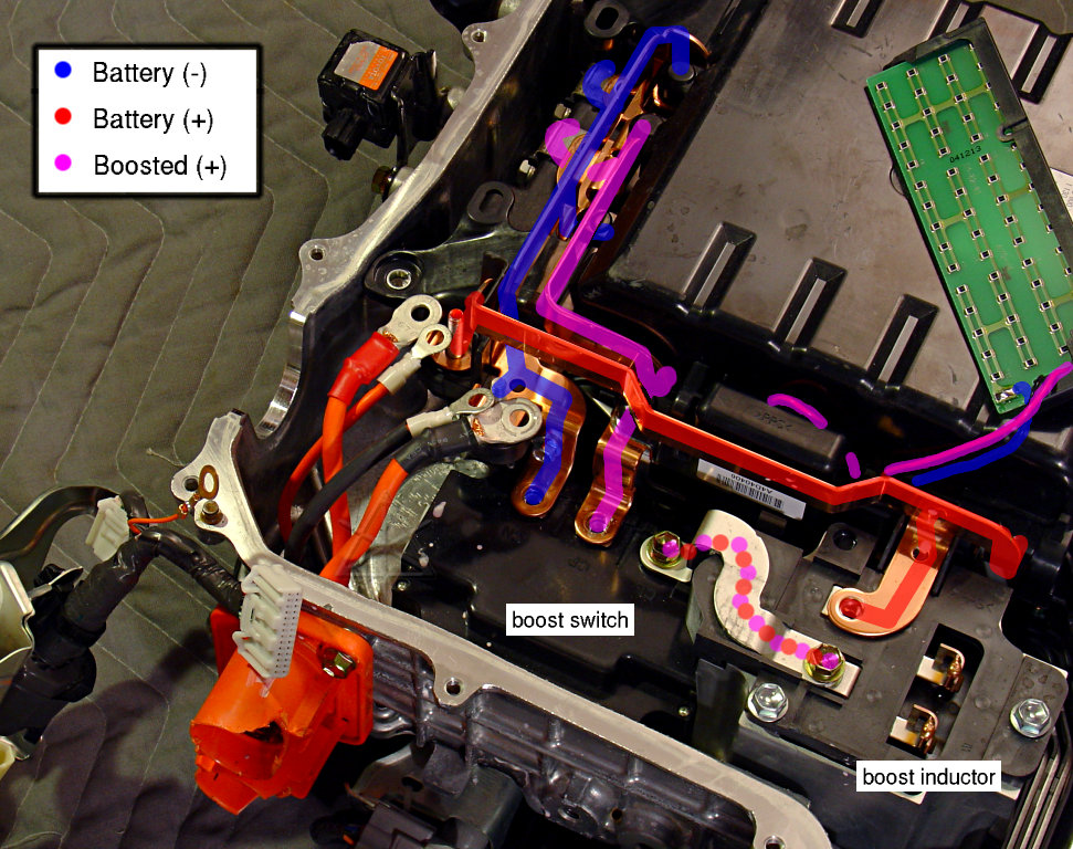
Quick electrical diversion: this is how power is routed to the major
components.  Battery positive heads right over to the boost converter, where
a large inductor and switch boost it up to as high as 500 VDC.  That boosted
voltage is what feeds the motor control block.  The bus bar paths are a
little oddly convoluted, probably to adapt to the capacitor connections
and where they hook into the motor-drive module underneath.
|
|
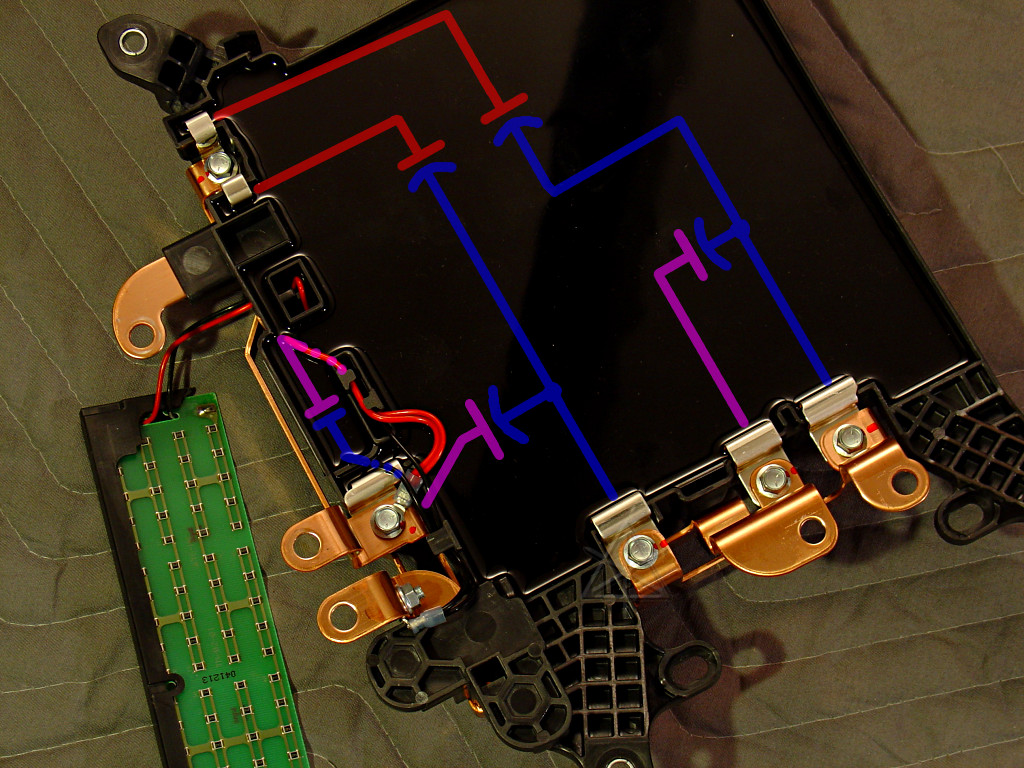
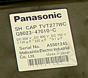
The capacitor block, all potted in semi-hard black encapsulant.  Using the
same color coding as above, I *think* this is how it's internally wired.  The
various separate negative and positive terminals are externally ganged together
by the bus-bar connections.  The larger caps filter the boosted voltage.  The
label doesn't really indicate whether the doubled-up caps make the values
listed, or there are two of each inside.  The 0.1 uF is held in a little wart
off to the side, fed by separate wires.

So, what's that little green circuit card with the black dots that's been
floating randomly around in the last few pictures??
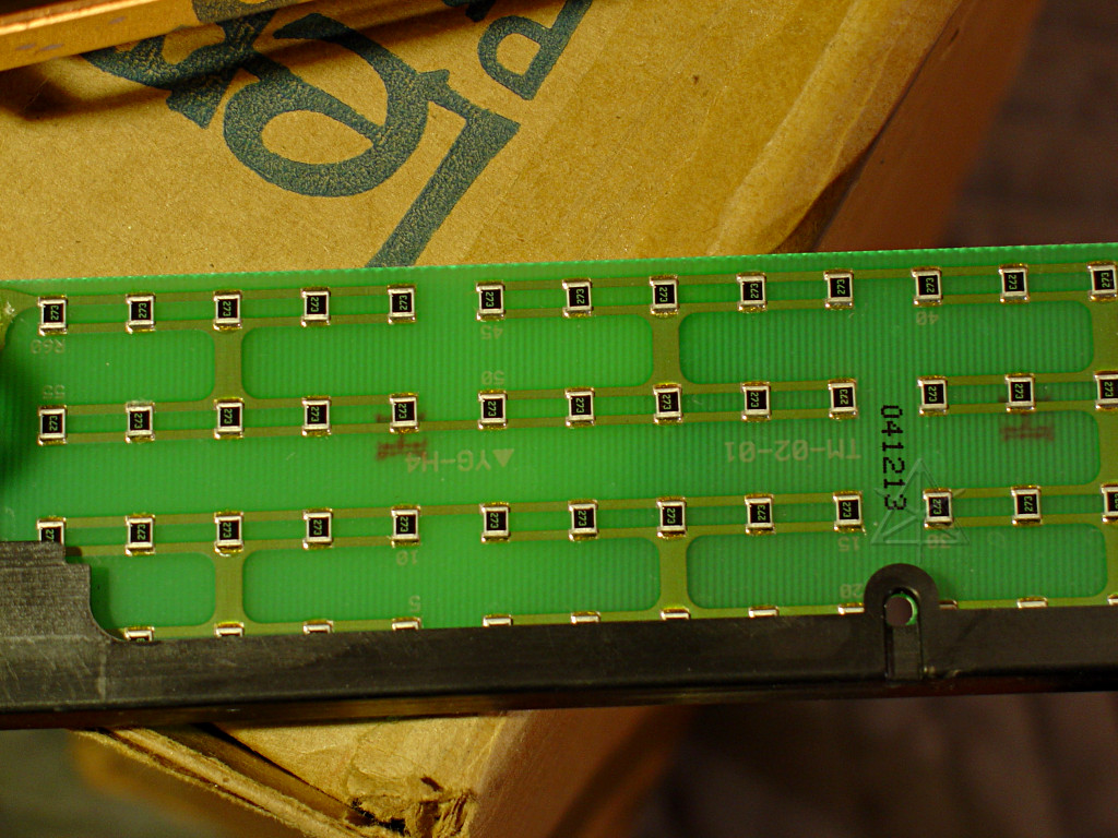
Answer: the main bleeder resistor.  An odd construction, to be sure -- sets
of 5 * 27K chip resistors in parallel [5400 ohms], and a ladder of 12 such
groups [64.8K total].  This array would have to dissipate a maximum of 3.85
watts with 500V across it, but each chip resistor would be handling .064 W
each -- and note how they're evenly spread out on the board.  In theory, no
component would have more than 42 V across it, and there's probably enough
redundancy in the parallel groups that if one resistor went open, the rest
could handle the load without making a hot spot.  This is one way to put
together a power resistor and give it a lot of surface area as well as some
component-level robustness.

The reason it's floating around on the wires is simply because its support
bracket is broken.  Ordinarily it would be firmly attached to the capacitor
module, but this is one of the few parts of the "together" inverter that
got damaged -- broken clean off.  It will probably take some of that "super
plastic epoxy" type glue to get it reattached to the capacitor block.
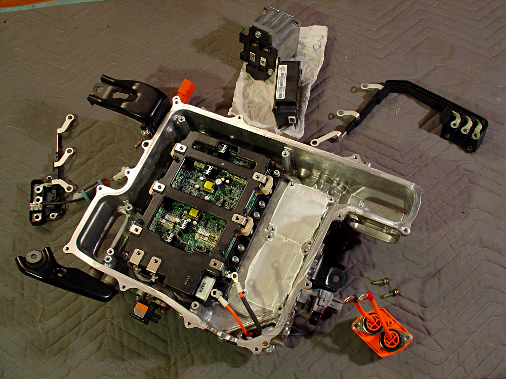
The boost components removed, exposing the thick layer of white thermally-
conductive heat-sink goop used to couple their undersides to the cold-plate.
Yup, the boost coil is actually coupled to the coolant loop too.

The 3-phase motor output leads are entertainingly snapped into plastic
modules that make it easy to remove them as a set.  The flat bar construction
of these and the bus bars is much easier to fabricate than sets of wires, I
would imagine.
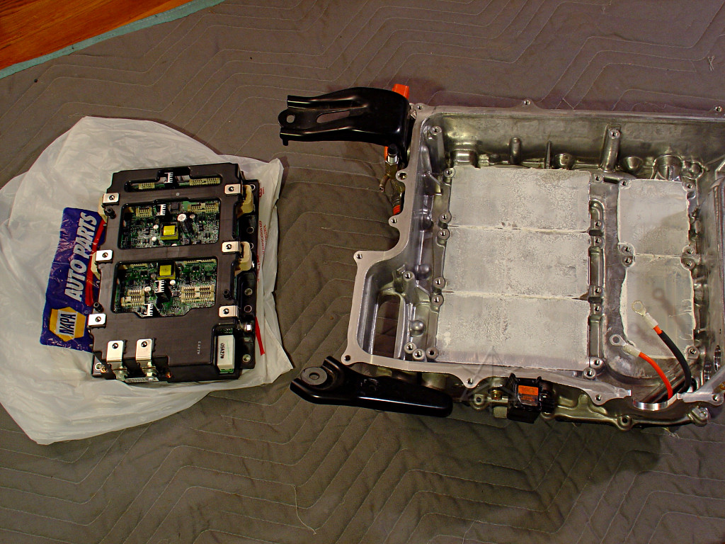
Next, the motor-power module, which is called the "IPM".  Its lower surface
consists of fairly massive thermal plates, which are also awash in thermal
grease, so the plastic bag is going to remain stuck to the underside for quite
a while.  However, I don't think you'll be able to get auto parts of this sort
from NAPA quite yet...
The upper half of the inverter case is now empty, so time to flip it over and
attack the other side.  There are a total of FIVE inverters of various sorts
in this whole unit, counting the boost converter.
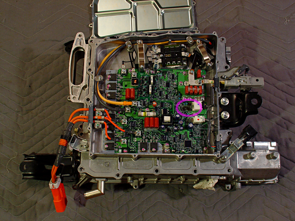
Under the cover we find the DC/DC converter and A/C power board.  This is
reasonably well documented in the Oak Ridge paper and elsewhere.  A tap from
the main 200V feed comes through a gland via the pale orange and black wires to
supply this board; there's a 30 amp main fuse for it hard-soldered on near the
middle.  This clearly takes construction cues from serious industrial control
electronics -- there's a conformal coating over the entire board to repel
dirt and moisture, and plenty of copper and ganged vias around the higher-
current connections.  Various IGBTs are bolted down to specific raised lumps
in the cold-plate -- six forming a 3-phase bridge for the A/C output, and four
in a push-pull bridge driving the DC/DC converter.  [ORNL got this count
slightly wrong, but a quick look at the part numbers and board layout makes
it obvious.]

The reason the electric A/C compressor is run from the high-voltage battery
rather than 12V is simply a matter of power.  Think about your typical
window air conditioner -- this is on par with that, and needs to draw 2 or
3 kW to handle the cooling load of a car out in the hot sun.  Trying to suck
that out of the 12V battery would immediately blow its 100A fuse.  But at the
220 volts that the hybrid system usually runs at in real life, that's on the
order of 10 or 15 amps -- easily handled by the 30-amp IGBTs that power the
3-phase compressor motor.  [Toshiba GT30J324, also noted by the Techonline
folks.]  And the significant advantage is that the compressor isn't tied to
engine RPM -- it can run at a variable speed, using only as much energy as
needed by cooling demand and scaling its consumption back appropriately.

The DC/DC has some fairly strange-looking transformers and filter inductors,
that use rectangular-section wire for denser winding packing.  The thick white
wire going out the right side is the main 12V output.  Battery voltage-sense
and regulation characteristics of the DC/DC are explored in more depth here.
At a maximum of 100 amps output, this will pull on the order of 6 amps from
the HV battery.  Some techs are still having trouble coming to grips with this
as substituting for the car's alternator -- which *doesn't* need the engine
running to charge the 12V battery!

So that's 15 amps for the A/C and 6 amps for the converter; it would be a
strange problem indeed to blow the 30 amp fuse feeding it all.

But something isn't quite right here; part of the circuit board near the
DC/DC control input appears to be dark brown rather than green [in pink].
Let's compare this one against the spare that came in the package...
 |
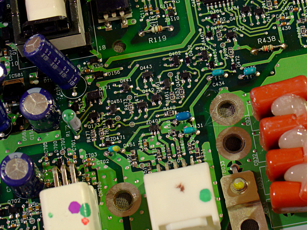 |
| Bad | Good [?] |
Looks like ZD401 had a really bad day, along with some other components.
Now, this inverter came to me with the understanding that the DC/DC converter
part of it was definitely not working.  I think we just found the problem.
Unfortunately the extra "good" board got parts bent and knocked off it in
transit, so it's unclear if this is fixable with parts on hand.  Trying to
determine exactly what happened and the condition of the spare will be left
for later.  There's other exploration to be done first!

While we've seen plenty of pictures of the inverter electronics in various
sources, there's another area just one more layer down that is rarely, if
ever, detailed.  Hang on, we're entering an uncharted part of the galaxy.
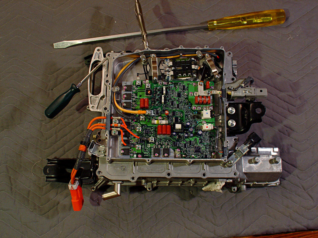
I want to finally open up the actual coolant channel.  The two halves of the
inverter shell are held together with many bolts and what looks like a
serious application of silicone RTV sealant, which is one reason we haven't
bothered getting into it at previous opportunities.  Now it's time, presumably
with the leisure to scrape the halves down and apply new RTV if it's ever
going to go back together as a working unit.

For this we need Big Tools.  A couple of halfhearted efforts to pry the
unbolted halves apart with normal hand tools seem laughably ineffectual, so
I figure it's time to haul out the Screwdriver.  This qualifies more as a
large pry bar -- it's the two-handed Highland Claymore of screwdrivers,
and the only defense against it is to have a particular size of Phillips
head.  It was given to me mostly as a joke by a friend years ago, and it's
been sadly underused in the interim, but maybe here's a chance to give it
a sweet taste of the cooling system's not-so-fresh lifeblood.
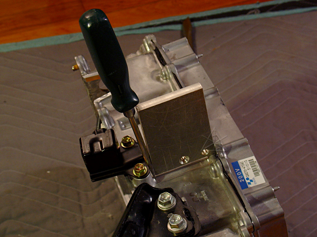
But in the end, sweeping romanticism is for naught -- it turns out there just
aren't all that many appropriate pry points around this seam that wouldn't
just break off parts of the casting.  What's finally doing the trick is a
slow and steady approach with modest gear.  I found an aluminum block just
the right size to go in between two of the stronger prominent features on
either side of the seam, minus epsilon.  Epsilon is filled in with the small
screwdriver blade, tapped in somewhat firmly, and then we just wait a while.
Tap in a little more, and wait a while.  I think I can just barely see a
slight separation in the halves, which hopefully isn't just elastic expansion
of the RTV.  Tap in a little more, and wait.
While we're waiting, let's review how the coolant flows through this system.
The freshest [coolest] liquid enters the inverter and passes under the main
power transistor arrays first -- the items likely to heat up the fastest
under high-load conditions.  Then out through the reserve-tank, through the
pump and down past both motors via closely-coupled passages at the windings,
and then finally to the dedicated radiator section again.  The pump runs any
time the car is in IG-ON or READY states, implying that it accumulates many
more hours than, say, the engine does.  The pump is a critical component --
and yet if it stops running, the only warning would be increasing inverter
temperatures -- there's nothing like a flow sensor for this loop.

Tap the driver in a couple more times, and finally the seal is starting to
break.  Semi-vigorous prying is still necessary around other areas of the
junction to finish opening things up, but *finally* the halves separate...
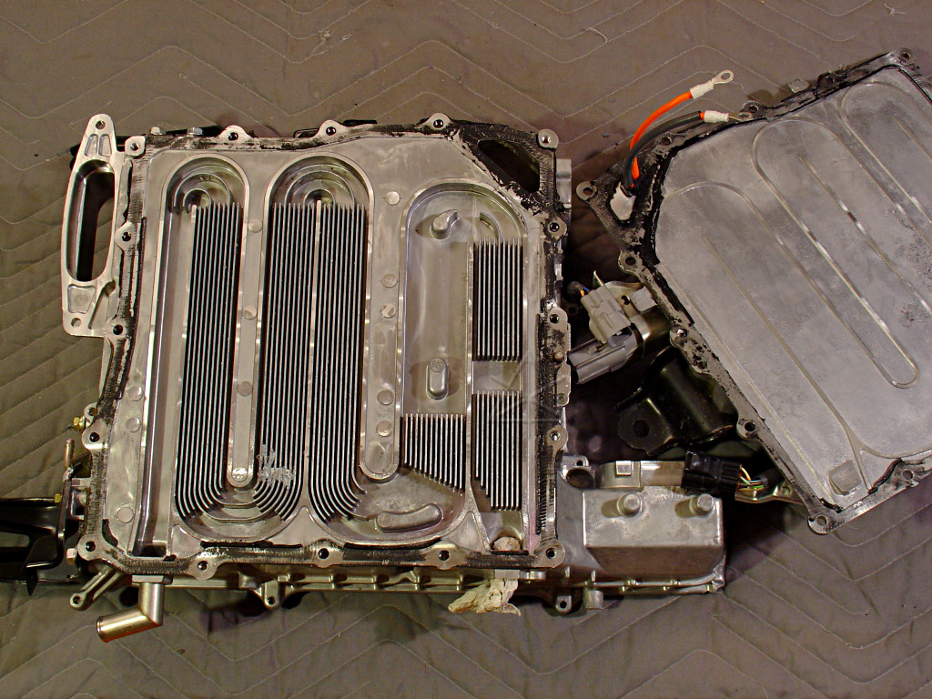
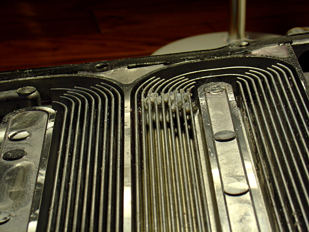
... to reveal a sight seen by very few human eyes outside of Toyota.  Take a
good look at the big picture for the full effect.  ORNL didn't get here, at
least not that they documented.  Our tech-training sessions never saw this.
Nobody on the forums has ever mentioned anything or sent pictures.  So here it
turns out that what I assumed would be in effect simple piping is actually yet
another carefully-engineered part, that reflects attention to fluid dynamics
and optimized thermal transfer characteristics!  Heaviest finning lands right
under those three big IPM baseplates, bathed in that fresh-from-the-radiator
coolant.  The finned areas under the boost inductor and switch are somewhat
odd but clear in their purpose, and apparently the inductor is expected to
dissipate more energy than the switch.  The DC/DC and A/C transistors mostly
get picked up by the first leg of flow from the inlet [lower left], but
evidently don't need nearly as much heat exchange capacity.

Now, what's that patch of discontinuity near the bottom? ...
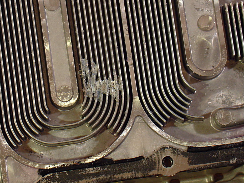
Apparently a bit of muck has accumulated here, and appears to be blocking
a large proportion of the passage.
Getting some light behind it reveals that the fins aren't completely blocked,
but why this muck is there at all is pretty mysterious.
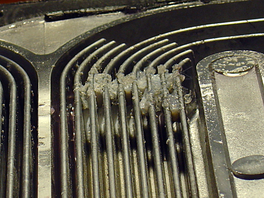
The stuff is sort of pale and jellylike, and seems to dissolve away to
nothing once rubbed lightly under water.  It doesn't feel like antifreeze,
it's probably something else.  Bottom line: gross.
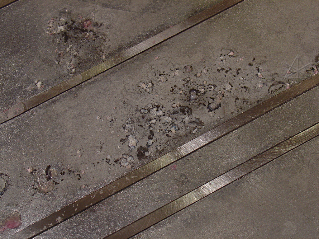
And it's evidently either corrosive or a product of corrosion -- here's the
accumulation at the same spot on the other half of the casing ...
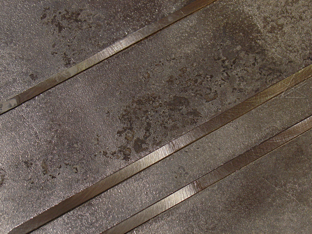
... which when washed away and scrubbed leaves permanent evidence of having
attacked the metal.  The reason this is particularly interesting is TSB
EG017-05, noting coolant leaks INSIDE the inverters in some '04 and early
'05 cars -- coolant would get into where the electronics sit, and the first
indication would be high voltage leaks to ground and codes like P3009/526
thrown.  If some contaminant or even component of the coolant starts corroding
the flow channel *and* blocking fluid passage, there are probably plenty of
places where a leak could spring.
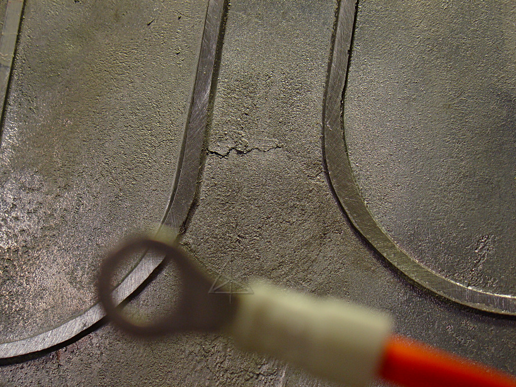
The probability is even higher if the inverter case already comes with spots
that might corrode through sooner than others.  The quality of the base
casting seems to be a little inferior -- there are quite a few flaws and
fissures in the surfaces that run pretty deep.  Perhaps Toyota outsourced the
castings to some company with QC not quite up to the same standards, and didn't
realize what they were getting back for another year or so?  We'll probably
never know, other than seeing that there was a "production change" between
certain VIN ranges as listed in the TSB.  There may have been a few personnel
changes to go with that.
This concludes exploration of the inverter case itself, for the moment; next
we'll move on to see how some of the modules are constructed.
Next: Component teardown
_H* 070522