House energy retrofit project 13

The whole issue of overhangs was now on everyone's mind a little more, and I wanted more information on what was structurally possible without running into problems with window sightlines and trim. For the front and back, yet to be determined, nobody had really asked me what I would like to try for in general. I heard at least one opinion on how larger overhangs to the front and back would somehow look funny relative to shorter ones on the gables, and dismissed it. One of my salient points in design thinking was a nice big overhang in the back to help protect the infrastructure stuff under there -- the A/C condenser, the ventilation ducts, and basement bulkhead area. Everything I'd read about best practice for seasonal sun shading said use big overhangs in key places to block heat in the summer and let it in over the winter.

I drew up a little plan view of the back roofline with potential overhang areas shaded in and decided to ignore the naysayers, size *does* matter here and I knew how I wanted to configure that area.


[Click any image for a larger version.]

    Declination

Figuring seasonal sun angles At my latitude of 42.4 north, the sun's summer solstice angle of 23.4 degrees doesn't quite put it straight overhead but still respectably high, and a bit lower by the time we're into the hot part of summer. A little back-of-envelope geometry later I knew I'd need a *minimum* of 18 inches of overhang to decently shade the upper windows for most of the summer, and bigger would be better. How about two feet? The house on the lot behind me had something even larger than that on *its* shed-dormer structure.

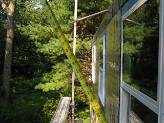
I hopped up on the scaffold out back for a longways look at the whole area in question and take some actual measurements. I dropped a piece of strapping onto the roof deck and hung it out exactly two feet, understanding that it would actually sit four inches higher than this once the dormer got foamed, and noodled some seasonal shadow lines.


Templating a 2-foot overhang I left the piece of strapping up there, and by mid-day the shadow of its end perfectly illustrated what I was after. In the absence of being able to work this out with the GC, this would be my tool to show the crew next time they were here -- I'd just point up at this and say "that's what I want, 24 inches".

    Day 8

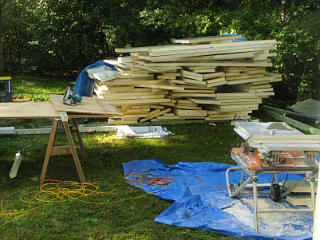
Bigger foam pile Construction wasn't up to that point yet, though, so today's project would be the cheek-walls to either side of the dormer. That would involve a lot of funny-shaped foam cuts, which they were hoping many of could come out of the fairly generous scrap pile that had accumulated.


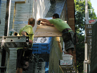
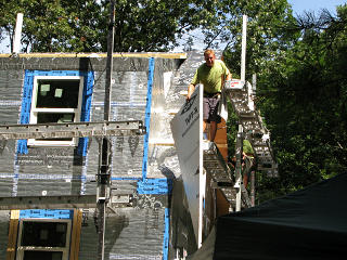
Working plywood up cheekwalls The one-foot side overhang would be maintained to match the front, and the plywood was again started a little way up to leave attachment space for whatever the rear overhangs on these little strips would be. They would likely match the front, giving symmetry to the steeper-pitch parts of the roof.

Here the roof-to-wall transition had already been done and buttoned up, and the outer row of screws under the leaning guy's right elbow went down into the original gable-end rafter of the house -- now sitting four-plus inches inboard of the end wall plane.


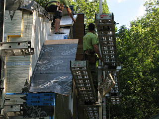
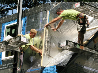
Foaming wing roof areas As on the front, the assembly of foam, plywood, and Grace proceeded upward toward the peak.

The nordic peak goes Handcutting the roof-split angle
It was time for the little nordic-hut peak to get chopped off and replaced with meeting the new foam layer coming up the back. At the pitch split, hand-carving the last pieces of foam to wedge in there seemed to be about the only way to fit things up. Note how the shed-dormer roof foam was already extended out to the side four inches here, to eventually match flush to the layers that would come up the cheek-wall.

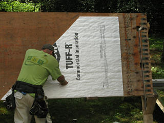
Cutting arbitrary foam angles The cheek-walls needed a bunch of odd-angled pieces, matching between the 45-degree and 22-degree rooflines. It wasn't that hard to pre-cut some of the shapes -- here the guy on the ground measured and snapped a line across the foam, and careful hand slicing following the line made a perfectly acceptable edge even without a t-square to cut against.

Not everyone on the crew carried a chalk line, so the couple they had between everyone got thrown up and down quite a bit as need dictated.


A big triangle Dimensions of simple pre-cuts to cover large areas could thus for the most part be verbally described air-to-ground, cut, and handed up. Our easel-master was a busy boy that morning.

Trimming cheekwall foam But then when pieces in the next layer needed to be completely different to stagger the seams, that got a bit too complex to vocalize and it was easier to call for something that roughly fit and trim it down in place.

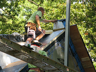
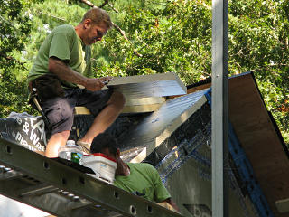
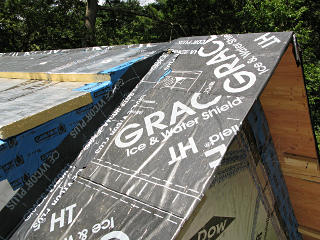
Gable peak all flashed up By mid-day, one side was done and all flashed up, restoring a simpler shape to the pitch split.

The overhang ply met in a way that placed its peak slightly higher than the rest, which I figured would eventually be leveled out by the shed-dormer over-roof but in the long run never quite got matched. That actually made the roofer's life more difficult later. Prime example of why trades need to communicate with each other.


Funny foam attachment They moved to the other side of the dormer and did the same, possibly in a slightly different and more optimized sequence now that they had a good workflow going on it.

Some of the shapes to attach and then cut off were kind of amusing in the interim, but it's what the guy on the ground could find quickly.


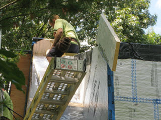
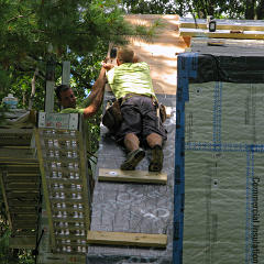
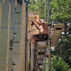
Working up the strip With the staging brackets necessarily attached down fairly low under the work area there was a limit to how high they could pump up, so cleats to aid climbing were attached to the new over-decking as they worked upward.

More holes to patch...


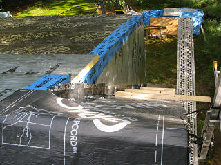
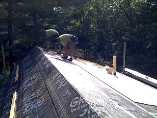
View from the other peak After they'd left for the day I went up to check out the completed transition from above. The Vycor along the endwall looks like a reverse flash, but the roofing and siding would later go over it later and make it a proper one. With their previously demonstrated adherence [!] to meta-taping such junctions it was a little mysterious why they didn't tape the top of this one. Maybe the Vycor sticks and conforms better than regular ice & water. Nonetheless, another in a host of good reasons to have a weather-protective overhang above all this.

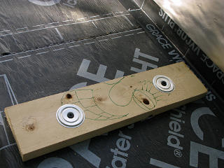
Someone was bored... I spotted this on one of the cleats. Someone must have been bored...

    Day 9

The GC finally scheduled a site visit to come check the progress of the job, at which point we could also go over a bunch of stuff on my punch-list to be officially figured out. The guys on site all worked for a subcontractor for the main company I was financially dealing with, sort of a consortium of a few different green-building outfits in the area. While it was clearly in the best interest of the GC staff to keep tabs on the ongoing jobs and what their subs were doing, they had just spent the previous few days out at Joe Lstiburek's summer camp soaking themselves in building-science geekdom and were understandably less available. But this week they could finally catch up to where we were.

So with everyone slated to descend on the site later this morning and get all the design stuff hashed out *and* finally bring my new side door with them, it was probably going to be one of the more chaotic days of the job. What I really didn't need was any additional headaches on top of that.

Thus, this was the completely wrong day to wake up and discover that my camera had bricked itself. Dead dead dead, no power-on, not even with a fresh battery, zip, a big nothin'.

This was my faithful Canon G9 that despite a recurring issue with its zoom spring had been rock-solid for me through the years without any sign of trouble, and then -- boom. Turned out to be a known hardware problem with this particular camera, and I wrote up the autopsy later on. But right now I needed to be able to capture at least some of the day's doings in pictures. I managed to limp along for the next day and a half on the cellphone cam, and then borrow a small succession of better units from friends. So that should explain a fairly obvious drop in picture quality starting here. Some of the cell-phone shots were passable only after a *lot* of postprocessing to rescue what I could, but the next couple of days in general yielded far fewer decent shots.


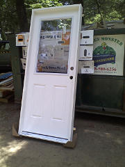
New side door arrives The door spec had been another sort of last-minute conversation. One bore or two? Still want the plain half lite with no muntins? Is white okay? I thought we had this all figured out before. At any rate, before they showed up they had stopped by their usual lumberyard on the way out and picked this one up.

They also brought along the first few boxes of siding, which were stashed aside for the moment.


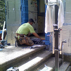
Laying sill pan A couple of guys pulled the hunk of plywood off the side opening and got started on installing the door. A metal sill pan definitely went in here, no mystery pictures this time.

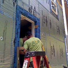
Shimming doorframe This frame got a proper set of shims to position it. It takes a bit of tweaking on those to get everything level, plumb, and square and then hope nothing shifts during later steps.

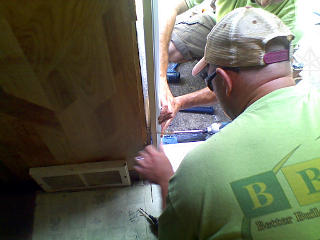
Fastening through shims The right way to fasten in a door appears to be *through* the snugged-up shims with long deck screws into the framing, so nothing places undue stress on the frame to rack or bend it. You still can't go nuts on tightening, though.

Shims sticking through slot Even with a proper solid installation, the door's attachment to the house looked really tenuous with all the gaps around the opening. Those got temporarily stuffed with some foam backer rod later for nominal bug-blocking. Once I could watch it a couple of times, I had a much greater understanding of how a door gets installed in a wall -- it's really not that complex but could be easy to screw up without due care.

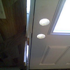
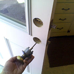
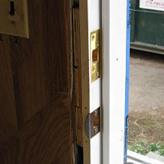
The nominally "fiberglass" door unit turned out to be fiberglass cladding over a wood and foam core, with the cross section clearly visible in the lock holes. This didn't appear to be an actual ThermaTru door like we had talked about getting ... in fact it didn't seem to carry any particular brand at all, and may have been simply assembled in Maki's shop from disparate parts. The sill had a shipping protector labeled "Endura Products" on it, and the hinge edge of the door itself said "Masonite". At least researching the latter turned up a chart that implied a U-factor of 0.28 [aka R-3.5] for this one -- not great, but probably on par with the old one which *was* a ThermaTru. At least this one's window was double-pane, but not filled with any exotic gas mix.


Old locks can be re-used The door came with no hardware and the builders didn't seem to have any intention of supplying any, so locks would be my problem. Fortunately it's an area I have, ah, fairly extensive experience with, not to mention a healthy stock of parts kicking around. With a typical 2-3/8" residential-grade backset at the bores, I determined that I could easily re-use my old knobset if needed and found enough compatible parts to put together a deadbolt as well.

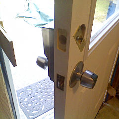
Simplex back in place However, for continued yucks I decided to re-install my old Simplex instead which is actually designed to be compatible with the dimensions of a typical dual-bore setup. Since I'd set and given a door combination to the PM at the beginning of the project anyway, that would still let him be able to get in if for some unforeseeable reason I wasn't home some morning.

They'd left all the shims sticking out on either side for the moment, and I had to be careful to not impale myself on them while going in or out.


Foamed around the toilet stack Meanwhile, the rest of the crew was topside foaming up the shed dormer roof. Except for the unsolved small bits around the front door sill, this was it for foam -- the house was now almost entirely encased in its big new beer-cooler!

At this point we had completed our site walkaround and after the GC did a little geometry exercise, determined that not only would the two-foot overhang on the back would be just fine, we could do a fairly generous 17 inches on the front and matched on the two little rear wing-wall pieces and still clear the front door and windows by a reasonable margin. And I finally got everyone aware of the special attachment points I'd need on the exterior walls -- for the ventilation duct supports in the back, and the new electric meter box on the side right over my pass-through.

We also talked a little about roofing, concluding that it would be pretty much up to me to figure out what I wanted. I spent some time that week poking around their preferred manufacturers' web sites, specifically Fabral and ATAS, and doing a little more research while gradually working toward a decision and trying to avoid feeling rushed on it.


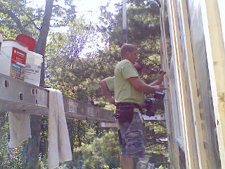
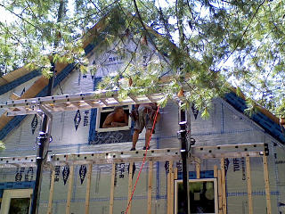
Finding more studs along back Instead of plywooding the shed-dormer they decided to finish out the day applying more strapping, which ran into some interesting issues. With the dormer most likely being a retrofit replacing an old 12/12 rear roof, what we thought might be real balloon-framing was not the case at all and the studs did *something* weird and unexpected at the second-floor boundary. None of us thought to check that and generate a set of markings for the upper-floor framing while everything was stripped off and visible, so a bit of hunting around was needed to locate the upper set of studs and follow them up with the strapping, which led to a certain amount of hunt-n-peck with the long screws and which got into a few interesting side-effects later on.

    Day 10

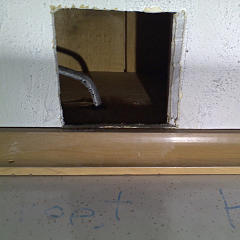
Hole in ceiling for electrical box With a side door back in place my thoughts turned to what else I was going to do around it, particularly for the light I was intending to install over it where the old wire was still hanging out. My ideal solution would be one of those motion-detector lights but rewired to also kick some sort of beeper inside, so I could tell audibly from inside when it got triggered. To this eventual end I got out my brandy-new jab saw that morning and cut an electrical-box sized hole in the kitchen ceiling, through which I could see said wire going out through the wall. In theory this would make rigging it all up easier, even if I didn't have a solid design for it yet.

It also reaffirmed my general loathing of doing *anything* with drywall.


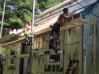
Handing ply up to shed roof The guys arrived and work on the shed-dormer continued, as they cut, pre-dimpled, and handed up sheet after sheet of plywood. These were a little heavy to be throwing up to each other; the ground guy carried it about halfway up the ladder until the up guy could grab it and horse it over the edge.

Plywood onto shed This part of the roof was *far* easier to work on. No cleats or climbing assists needed.

Again, the lower edge of the ply was left a foot-plus shy of the edge of the foam.


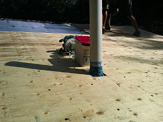
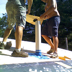
Ply cut around pipe Upon hearing about my camera issues, one of the guys on the crew was kind enough to get a few shots on his iphone and mail them to me later. This is one of them, showing the plywood cut around the stink-pipe and how it had gotten flashed to the foam underneath.

Flashing piece for around pipe Once the ply was down, *more* flashing went on around the pipe as the Grace was rolled out across the completed over-deck.

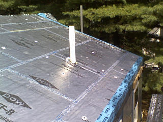
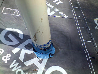
Dubious stink-pipe flashing job After which this stink-pipe was well and truly buried. But it still had a little bit of flexibility through all this and the rubber coupler underneath. To me this final layer looked like a potential reverse flash on the down side, but it's all stuck together with the bitumen and whatever happened on the roofing around here would layer over all of it.

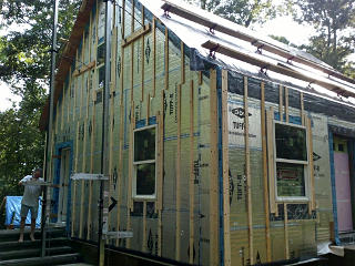
Finding east-wall studs The stud-location mysteries continued on the east wall, inside of which is essentially a storage/stock room with a lot of shelves [read: more of my hoard] and relatively difficult access to the interior wall. A combination of using a stud-finder inside and looking down from inside the attic eventually managed to find them all, and strapping could proceed.

This surprise discontinuity in the framing was really kicking everyone's ass, but they had to make sure to locate all the studs for solid attachment. Hindsight says double-check stud alignment at every floor boundary while the sheathing is open.


That crazy homeowner And here we see the east-wall result, a crazy interlacement of inconsistently-spaced furring with a break where the floor is. And the equally crazy photographically-challenged homeowner scribbling down an email address so the guy [who also took this] could send me his pictures.

Another noteworthy thing here is the doubled strapping configuration at all the corners. This is to provide plenty of nailing surface for siding corner posts and similar parts.


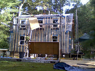
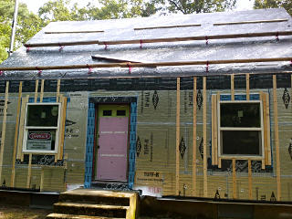
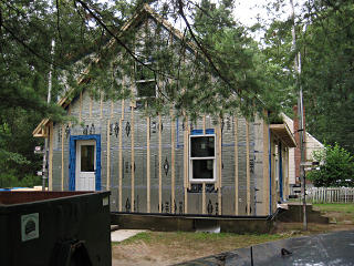
Front view From the street, the "curb appeal" side of the place had become a little bizarre itself -- a study in pink, green, blue, silver, plenty of product advertising, and work planks vaguely reminiscent of the silly wings on the back of riced-out cars. And this was precisely the evening that my electrician and his wife took the opportunity to come came by and visit the place to see the progress. They were pretty amused by it all.

At least the front wall only had a single run of already-located studs and the strapping would be easy to finish up later. It wasn't in place by the front door yet because the area around the stoop wasn't foamed, and they were still figuring out what the overall best solution there would be.


    Day 11

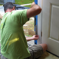
Sawing off door shims flush The next morning, the protruding side-door shims were cut down flush using a fine-tooth Japanese hand saw that's really good for precise trim work.

I had also borrowed a somewhat better camera from a friend by now, and was still getting used to its limitations. Such as not having full manual mode, which might have helped me freeze the action a little better here.


Backer blocks for lock strike plates I scrounged up some small bits of plywood and inserted extra blocking behind where the strike plates would mount, to connect that whole area of the doorframe firmly to the rough opening. The guys assured me that the extra blocks wouldn't interfere with the air-sealing later on, and I was careful to not rip up the Carlisle while working them into a fairly snug fit and pre-drilling some holes. Both the deadbolt and spring-latch plates got nice *long* screws that went through all the layers deep into the framing but with the blocks in place, wouldn't distort the doorframe.

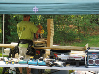
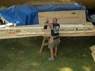
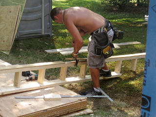
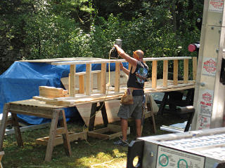
Cutting parts for overhang ladders Today's primary project, though, was to start on the various overhangs. These would be constructed in typical "ladder" fashion, with framing to form a structural box and extend the roof. This needed a whole bunch of identical crosspieces cut, which our guy here was industriously cranking out.

Figuring overhang dimensions The wing-walls would get little overhangs of their own, which they decided to do first as it would also anchor the gable overhang structure. Note that *now* is when the lowest piece of plywood would go on, after being sized to the overhang dimension now that we finally knew what it was.

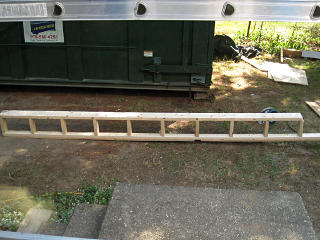
Pre-fitting mini-ladder A mini-ladder was constructed and fit up. It took a bit of noodling to get the right dimensions for this, and I think they made a couple of different tries at it.

At front and rear eaves like this, the framing and the ply form a triangular truss structure that's wikkid strong once it's all fastened up. Where this ply was lagged down into the rafters would probably wind up with the highest side loads on a screw-through-foam assembly, especially when someone was putting weight on the edge.


Building ladders Ladder ready, almost
Meanwhile, a new guy came on the crew and was tasked with constructing the gable ladders. Lots of nailing, but the air-powered framing gun made relatively short work of it. This one got narrow plywood rips added onto one side as a spacer.

Ladder doesn't need this piece However, the spacers were apparently not needed [something about the existing strapping thickness up above] and got ripped off again.

The uneven ends and hanging pieces are deliberate -- the ladder got made in two pieces, and two similar half-assembled ends would nest and mate up in the middle to form a much stiffer joint between the two halves.


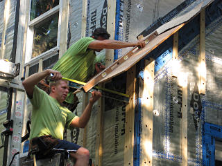
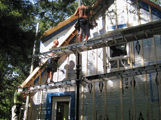
Installing ladder up gable They got it all figured out and the ladder attached, screwed all the way into the original framing. Note that while most of the assembly is from 2x4, the outer board is a 2x6 with the excess on the top to meet the plywood. With all the foam in place, the upper 4 inches of the wall surface now has no "meat" behind it. The ladder orientation rides the inner 2x4 a little lower so it aligns with the framing inside all the foam -- otherwise the screws through it wouldn't have anything but foam to bite into, which totally wouldn't work.

Shadow board goes on An extra bit of strapping formed a "shadow board", a feature I had just learned about during the chat with the PM. Here it's clearly doing its job making a shadow. The real purpose for this is to add an extra Z-bend into the trim metal to go over all this, which stiffens it and helps prevent the thermal rippling that would more likely appear in a large flat surface. We sometimes see buildings with flat wide trim that looks all wavey -- that's why: large expanses of flat metal that over time refuse to stay flat. The shadow-board contour is an easy way to prevent much of that issue.

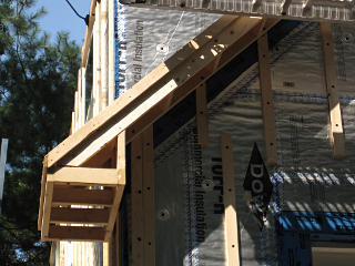
Wing-wall overhang framing Additional framing tied these two ladder pieces together and formed the return and soffit box for the wing-wall roof piece.

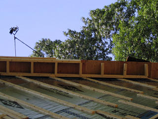
Peak overhang framed up Fairly soon the gable overhang was framed past the peak. Here's why the plywood spacer wasn't needed: the ladder mounts *over* the strapping, already putting it 3/4" out from the foam plane. Attachment screws run in through the strapping as well and lock everything together as an integrated structure.

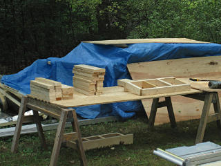
Parts for the large ladders More parts for the larger overhangs had been cut and put together in the meantime.

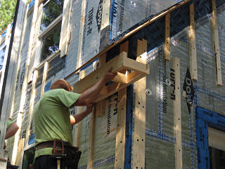
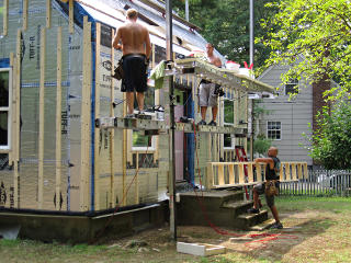
Handing up front ladder parts They moved around to the front, and the guy building the ladders had the first half of the large front overhang ready for them.

Attaching overhang framing This got hoisted into place and attached, same lag-into-framing method.

Front ladder in place The non-adhered tail of Grace hanging over the front edge got flipped up, and the lower course of plywood went on abutting what was already there and hanging out the required distance to meet the 17" ladder. The second half of the ladder and the rest of the ply went on and it all got an additional lowest run of Grace flashed under the one above, and the front finally had an overhang again! Finally, maybe a little better rain protection.

East side all furred up In fact the house was starting to look like it might eventually have a real roof again.

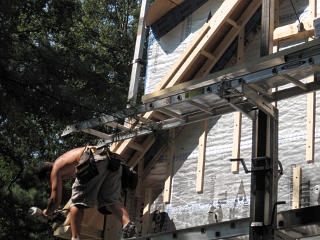
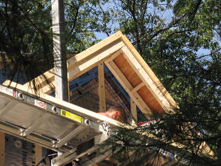
Partial gable ladder Sort of an art shot: the starkness of the scaffold bracket hanging out against the sky struck me as somewhat amusing. It could almost be mistaken for a camera on some sort of tripod from here. The front part of the gable ladder also didn't quite get finished that day; this shows how the mating crosspieces are placed so their ends straddle the seams where the long pieces meet. That all gets nailed up as they get fit together.

Making the *really* big ladder The new guy spent most of the day making ladders, and finished up by starting to build the *really* big one -- the two-footer for the shed dormer.

I think if I was doing this I'd want a milk crate to stand on. Those air-powered nailguns are kind of scary.


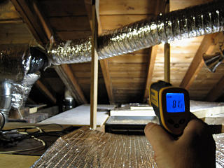
Attic is already cooler In a different sort of shooting, I went up and measured the attic temp that afternoon, after the foam had been on the shed dormer for a couple of days with a nominal bit of cooling going on in the rest of the house. Already a significant difference from the hundred-plus from two days ago! And that was still with the sun hitting the black layer of Grace HT all day. The new insulation was clearly doing its job.

I had run a couple of quick-n-dirty ducts out from the ex-chimney point, to try and collect air from up near the ridge peak and farther away from the hatch and promote better circulation. This helped exhaust a lot of the leftover heat in the air and the structure, but it took a while and placed the highest load I had seen to date on the cooling system. Thermal dynamics get more interesting when the *entire* old framing and wall structure is now thermal mass contained entirely inside the envelope.


Next section   (14)
Index

_H*   121201