Perky pipes
|
Another "make it nice" project I wanted to get done was to finalize the
HRV ducts and actually use those handy attachment blocks they'd put
into the siding. In searching around for various commercial
pipe brackets I looked at some of the offerings in the
F.W.Webb catalog
and realized that these were really so simple and obvious
that the best answer was to just build my own. Out of what, though, since
it was going to be outside? My usual knee-jerk impulse toward steel
packing-strap wasn't going to work as that wouldn't last very long.
Aluminum might not be quite robust enough and there was the immediate
question of what kind of fasteners would be suitable with that. On
the other hand, galvanized with zinc-plated hardware would be stronger
and reasonably corrosion-resistant and I had various bits of sheet steel
kicking around including some the HVAC installer had left me, so now
I had a plan.
|
|
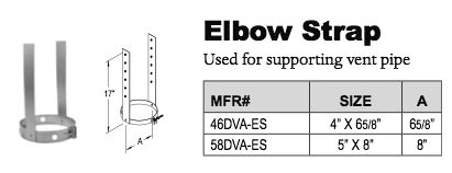
| The next problem was what to use as rain hoods. There was no way I was going to hang a 180-degree "U" of two more heavy PVC pipe elbows on top of my risers, even though we see similar constructs sticking out of septic tanks and sealed-combustion furnaces all over the place. That's what the HVAC installer had in mind when he brought the parts, anyway, but that done in 6" pipe would be pretty monstrous. For a while I fixated on finding something with a 6-5/8" *inside* diameter as that would fit nicely over the outside of my PVC, and that knocked an awful lot of "six-inch" product out of the running. The only options in the target size seemed to be a bunch of B-vent stuff for gas furnace flues and such. But a cap whose neck would fit inside the PVC but also shelter the junction sufficiently well might do, which allowed consideration of many more types of termination. A whole lot of searching and phonecalls finally landed on some suitable vent caps from R.E.Williams, which turned out to be rather flimsy and still needed a whole lot of modification and addition of bug screen before they'd really work. But light aluminum right-angle caps would eliminate the need to put anything else on top of the riser pipe, keeping the weight and complexity down. | |

|
With the hoods on order, I could get going on the hangars. All I needed to do was cut some long straps and punch a few holes. With only hand shears for lots of long cuts, making the straps was sort of a whole-body exercise. |

|
Even though the bracket design would include an upward pull, I didn't trust the three-inch blockoff assembly or particularly the PVC cement junction to take the weight load of the riser so a couple of little reinforcement gussets got shaped appropriately and cemented in. This would really make sure the pipe kept its downhill slant. |

|
The brackets needed a little fiddling and a couple of extra holes punched on the fly, but the assembly turned out beautifully simple. Upward and inward pull could easily be ajusted by sliding the band on the pipe before the final tighten-down of the clamp screw. The modded cap would definitely keep out straight-down water with a generous integral flange that I bent down into a drip-edge all around. And the bottom of each elbow got a small drainage hole drilled through at the lowest point, still dropping well clear of the house. |

|
All in all a rather neat installation, I thought. Putting a filter bag of some sort over the intake in pollen season would probably still be a good idea, as bug-screen wouldn't filter the fine stuff. I'd figure that out when the time came. |
Well, blow me down

|
While I provided for three mounting screws for the caps I found that just one per would hold them in perfectly well, also making it easy to pop them back off which I had to do a couple of days later because the Synergy guys arrived to finally do a blower-door test on the place. It makes no sense to do an infiltration test with any enclosure penetrations still open, so the magic coffee cans swapped in to turn my vents back into walls. |

|

|
|
They brought the typical
Minneapolis blower door
setup, and thought the front door would be the best place for it.
I thought using the side would allow testing how well *I'd* done on
sealing the front door itself, but we also needed to see if the side
door was tight too so it really didn't matter. They assembled the frame
and clamped the whole rig into the opening, making sure to route the
outdoor sensing hose off to the side away from the fan blast.
It was obligingly a little chilly outside that day, which would greatly help in hunting down leaks. They say they only need a delta of ten degrees to get decent reads on the infrared imager, and we had more like twenty to work with. | |

|
For some reason the automatic "cruise control" on the DG-700 manometer rig wasn't working, and they spent a while headscratching over the manual and wondering why the fan wouldn't start up. Eventually they gave up on that and went to run it manually, and then couldn't get valid CFM readings at all as it kept just saying "low". They thrashed around with this for some time before realizing that we just weren't getting enough flow past the sensor for a valid reading. While this was promising in terms of the house being tight, it wasn't getting us a number. |
|
It took a bit of studying to learn this, but the flow sensor on the
Minneapolis fan is basically a pitot-tube ring mounted on the back
of the fan motor. Enough air has to be going *right* past that to
produce a readable pressure differential, and to help with that the
blower assembly comes with a set of insertable constriction rings
to narrow the flow path a calibrated amount. Trouble was, they didn't
have the smallest "Ring C" to put in even though we evidently needed it.
Apparently those have to be special-ordered from Energy Conservatory
to complete a setup usable on small, tight buildings. If you look at the
flow table for the Minneapolis model 3, ring B doesn't even start to
meaningfully register until something over 300 CFM, happily implying that
we were already under that.
But the Synergy fella had seen a C ring before and remembered about how big it was, and figured he might be able to hack something up that would at least give us a ballpark leakage figure. |

|
He cut a quick ring out of cardboard, wrapped the inner edge with a little tape to sorta smooth it down, and stuck it in. Now we were finally getting a valid reading, with remaining question being how accurate it might be. This looked like an *awfully* tight and turbulent passage, so it wasn't going to surprise me if it read erroneously high. Which part of "calibrated" were we failing to understand here, hmmm? |

|
We got 336 CFM, which for my volume of just under 15,000 cubic feet would be 1.3 air changes per hour at about 50 pascals pressure difference [ACH50]. That's actually not too shabby, but part of why we were doing this was to find if there was more sealing work left to do. They said that smaller buildings were harder to achieve low ACH numbers on anyway, which makes sense as volume increases faster than envelope surface area. There are those who would argue that ACH50 is meaningless, but the air exchange rate is still very relevant when considering ventilation requirements. See this musing and related for more on the confusing alphabet soup swirling around this topic. |

|
We left the blower running and went around inside the depressurized house to shoot all the potential problem areas with the IR imager and feel for air infiltration. Here I hadn't foamed up around the stink-pipe yet, but it looked like all those multiple layers of flashing products had the penetration pretty well sealed already. [I wiggled in there later and foamed it anyway, if for nothing else than to make the pipe a little more rigidly held.] We couldn't find any obvious leaks around the attic, although a couple of corner areas looked just a little cold -- that's pretty common, as despite all that layering complexity with foam and flashing it's still hard to get corners totally 100% tight sometimes. And they're often where insulation materials *can't* get fully interlaced just because of the way planes meet up, leaving an air channel between warm and cold even if it isn't directly connected to either. And of course normal occupancy would never impose this much depressurization on the envelope components, so a few tiny leaks won't pass a whole lot of air volume. |
|
A FLIR imager doesn't necessarily tell the whole story about airflow;
every visualized cold spot has to be checked with a hand or smoke pencil
or whatever to make sure it's not just conductive loss as remediation
for either scenario will be different. And cold air forcibly pulled
through a tiny leak and impinging on surrounding materials
for long enough might look like a conductive loss point without a
careful up-close test.
A big caution about blower-door testing is combustion flues, which are not only inherent leaks but send exhaust gases right into the house if the relevant appliances aren't shut down. If my chimney had still connected between the outside and the oil burner flue, this testing would have been pretty meaningless and probably would have sucked soot into the house. But now I had no flue worries at all, yay! | |

|
One real eye-opener for me was how leaky a *foundation* can be, especially
cinderblock. We think of a "solid concrete wall" as solid, right? Not
so, as any crack or crumbled bit of masonry can let substantial air in and
soil is actually pretty permeable especially when it's dry. The Synergy guys
have seen air leaks coming up through *basement slabs*. We found a few
spots around the basement wall where a cold draft was coming in between
the styrofoam panels, even fairly low down on the wall, implying that
there was a path somewhere through the cinderblock.
A few days later I went around and wire-brushed and concrete-caulked any of the larger obvious cracks and fissures in the foundation, which I'd hardly noticed before but now were bugging the crap out of me with my newfound air-sealing fanaticism. There was plenty more of that to come, too. |
At your service

|

|
|
Again, it felt pretty useless to bother trying to involve Verizon to get
the phone and fiber attached back to the house. I had explored the rake
area and had parts of the soffit and siding opened up in anticipation of
getting the power reattached, and had even put markings up the trim
metal to indicate heights off the ground. [Working from my "do not use
near power lines" all-aluminum extension ladder, of course.]
I came home from yet another hardware run with a galvanized ring lag-screw and a shackle and it was the work of mere minutes to install the ringbolt at about 13 feet up, leaving plenty of room for the electric to go in above later. It was easy to readjust the slip-clamps for a good catenary out to the street, and both lines fed into a nice drip loop tucked up under the overhang before heading down the wall. I made sure to angle the hole for the ringbolt so it would sit angled just slightly down and toward the street from the fascia, and ran it in through a blob of caulk right at the external hole. Downward would make sure water wouldn't come toward and in past the metal, and toward the street would somewhat relieve the almost right-angle bending moment on it and the wood. The ring and shackle had to sit an inch-plus out from the fascia, as the arrival angle of all these wires is pretty acute and everything needed to pass well clear of the sharp roof drip-edge. The relatively inflexible FiOS fiber and its minimum bend radius placed some limitations on the path everything could take, which is why it's actually tucked up under the J-channel. While I normally hate zip-ties for wire management they were reasonably appropriate here, and the one touching the trim was placed exactly at the corner with its tail hanging downward to help water drip off at that point. Subtleties no generic wire installer would probably ever think of, but these details make a difference. | |
Finally, a side storm
| When the Synergy guys had come by for the first blower-door attempt they also brought the storm door for the side, but got so ratholed in the air-leak testing they didn't have time to even consider installing it so they stashed it in the basement for some subsequent visit -- when they'd also come back with the right "C" ring for the blower. They had to order it. I didn't think about the storm door for a couple of days but then started getting curious about what was in the box and thought I should at least teach myself what comes with one of these. |

|
A little shopping around had led me to decide on an Andersen 2500-series
unit, with full height glass but a top pane that would slide down and
unroll the bug-screen from a hidden roller in the top. A slick little
system, as long as the spring roller or the screen didn't break. I passed
this knowledge to the GC who didn't have any prior opinions on storm
doors one way or the other, so that's what they brought along.
It had a lot of sub-packages inside, containing the latch hardware, the closer, various trim pieces, and a bunch of screws. And various installation instructions, which I started reading. |

|
I figured as long as I had everything spread out and room to work, it
couldn't hurt to put the latch hardware onto the thing which actually
involved a template and a bunch of fairly careful drilling. Their suggested
method is pretty sloppy and I'm sure most people don't bother to de-burr the
ugly resulting holes, but I had the leisure to do a nice neat job on it
with tighter clearances so the latch assembly wouldn't rattle around.
Then I got intrigued by the idea of putting the hinge side of the frame
on, and being far more careful with threading the sheet-metal screws than
usually gets done.
It's interesting that these storm doors use the euro-style lock cylinders, barely visible in the big pic here, and mounted upside down in the typical fashion thereof to make sure water and crud can fall down amongst the pins in a windblown storm. *forehead smack* |

|
One thing led to another, and I eventually
decided to just go ahead and install the
thing. A driving reason was that I knew the trim metal on one side of
the door was a dual layer due to the various odd assembly weirdness that
had transpired, meaning the "real meat" for mounting screws to bite into
might be hard to find and I didn't want to have to ride herd on someone
else to make sure they didn't miss that. It meant that the whole
frame would wind up with a little tighter clearance and shifted to
one side.
Working alone, I had to come up with some creative ways to hold the whole door up while aligning the mounting points. |

|
Pieces of the 3/8" grey PVC were the perfect size to shim it out, using one
at each hinge location so screws running in wouldn't distort the frame.
For a while the thing wasn't wanting to be plumb and I finally realized it
was because the trim metal and/or the Azek under it wasn't quite vertical
either. And it was pretty much all Azek in there that I was drilling into,
not wood -- I even went back to some of my own prior pictures to check.
And here we see the other problem: the whole door was too short! The necessary slope of the sill across the new thickness of the wall put the outer lip about two inches lower than normal. This must be a problem in all kinds of retrofits where walls get bulked out, and I still don't know if there's a generic solution -- I heard rumors that doors taller than the standard 80 inches are available, but they don't seem common and the GC hadn't made any efforts to proactively determine if one was needed or not. At least I didn't have to trim off the bottom of the frame. |

|
The tighter clearance led to a minor conflict in frame pieces that would normally just butt up, so I had to dremel a quarter-inch or so off the top piece. Eventually I got everything to sit satisfactorily straight and ran the rest of the screws into nice solid stuff behind the trim. |

|
The remaining gap got handily fixed with another piece of white coil
stock tacked onto the bottom extender with a little stiffening rail.
It turned out the inner surface of the storm was just about flush with
the lip of the sill piece, so that made for a perfect straight-down
fit. The learning
experiences from the front storm about drain paths told me to attach
it to the vertical surface rather than bang something onto the bottom,
so this would prevent anything leaking off the door itself from landing
on the sill or the wall. The addition of a bit of foam weatherstripping
and minor
hole-filling with aluminum tape at the corners made the whole thing
quite well air-sealed -- pretty funny for a screen door. But now when
either one opens there's a big damping effect from trapped air, which
once again lends that solid bank-vault feel to the whole thing.
[Pic taken much later, after we'd gotten some snow.] |
| The two bits of black tape on the sill piece are, like on the metal ductwork downstairs, to facilitate IR-gun temperature measurements to see if the caulked break between the two aluminum pieces is actually a thermal break too. Under nominally chilly outdoor conditions it shows a difference of three or four degrees -- not a lot, and probably at about the same depths as the thermal gradient through the wall would be anyway, but every little bit helps. | |
Return of the roofer
| With more of the major followup tasks getting completed, I really wanted to get the roof finished up. The extra panels had been on backorder for close to a month, and the poor guy's *better* bending brake had been sitting out in the weather the whole time. If I'd known it was going to take this long I would have brought it into the basement for him, but I thought he was coming back any day. |

|
I was still getting some of that annoying stray water leakage through the soffit areas over the west cheek-wall, probably from a couple of screw holes or Grace gaps I hadn't hit with the hasty run of Dow tape. It was only one small area so I didn't sweat trying to fix it, with the real roof completion imminent. |

|
Finally the roofer showed up one afternoon to deliver a box of panels
and check in, and I ran him through the litany of the little details I
thought were ghetto and/or wrong. He knew things weren't finalized
in several areas and promised to make good on all of it. A couple of
days later he came back to do the work, starting with pre-cutting and
forming the panels in the usual way.
It was a beautiful fall day, and the oaks had started their long drawn-out process of shedding leaves. It was definitely raking season, and I cleared a large area behind the house so he wouldn't be wading through piles of crunchy dead stuff. I also wanted us to be able to see anything that got dropped. |

|
As I'd observed before, he really loves getting himself in these precarious
positions. For the record, a rubberized hammer handle makes a good soft
mallet for tapping panels up into place and gives the user a little more
reach than trying to pull on them by hand.
Once the last panel went on, there wasn't any more nice sticky tarpaper surface to walk on so from then on it was all about the "try not to slide down" game. |

|
The shed-dormer roof was just a smidge wider than an integral number of panels, and we needed the custom-formed drip edge anyway. A panel got the appropriate lengthwise cut and pre-bend, ironically completing about *one inch* of remaining roof area and then diving over the edge. |

|
It actually needed even less than that, leaving no room for the usual hold-down clips, so he fabbed up some custom clamps to attach down the side rather than mess around trying to optimize screw placement in the shadow board. Even with the tiny nip of extra roofing area, the absolute minimum that could be bent in the brake, the last panel-ette was a little too wide to fit snugly. |

|
He needed something extra to attach the drip-edge flange to without
bending it way in, and I remembered that I had some thin strips of
Azek in the hoard upstairs. These were a little hokey but served
the purpose as spacers where they were needed. The drip-edge part
still wound up a little farther in than vertical, but at least it
was all *over* that dumb water-collecting upper edge of the trim.
He left my Dow tape run in place; no reason to pull it off if it was
helping seal things..
The ridge cap had gotten completed by now too, and he uprooted the main cap long enough to add an upward lip at the inner edges of both little cap pieces so they wouldn't be a reverse flash in under the main cap. Again, a little hokey and maybe not immune to wind-driven rain, but with the funny transition it was really about all that could be done. For some reason ATAS didn't have a good detail for that type of area when I grilled their support people about it. |

|
The roof completion actually didn't take that long, including the bits I
was bitching about. Just under the east-end cap we can see [big pic]
generous gloops of clear caulk into the partially exposed chicken-ladder
holes.
I went over things pretty closely after he left, though, just to take care of some last details. All of the shed-dormer drip-edge pieces, for instance, didn't really have their kicker edges pointing *outward* at all after being tacked down to the rakes, they were more like straight down. A drip edge is supposed to send water out *clear* of the fascia, not feed onto it. I went as far as I could practically reach along both shed edges and tweaked the whole thing properly outward. |

|
The roofer had done these little bent tabs to close off the open seam ends
instead of inserting the little clip pieces that ATAS had sent; we both
thought it made a cleaner detail. But he hadn't crimped them all tight,
and some were sticking back up at some open angle and providing a perfect
place for all kinds of stuff to hang up. I went along and fiddled them
all to lie pretty flat against their respective seams.
At some point I decided I was into diminishing-returns territory with regard to fussing with little details. For better or worse, at least I finally had a roof over my head. |

|
In the continuing process of raking, I kept turning up more and more tiny
little
scraps from the whole project. Every time it rained a few more bits would
surface, and raking brought out quite a bit more of it so I decided to
make a little display collection since I could pretty much identify every
material in it. See the big pic for the labels. Some of it I had
generated, but most of it was from the builders. I re-used a lot of
the screws I found, too.
I'm sure I'll continue finding this stuff for years to come. One thing I picked up far more of than I expected was the little cut-off caulk tube tips. That's *good*, because it means that they used a whole lot of caulk on the job! |
Yet more water control
| A few afternoons later a guy quite unexpectedly showed up to install the gutters. Communication with the GC was starting to really fall off as the real end of the project drew near, as he hadn't mentioned this at all and it was good that I happened to be home. This was one guy in a box truck, no helpers, and I expected that he might want some amount of assistance from me. |

|
He came with a lot of ladders, and set up two in the back and two in the
front. First was to get a measurement of the run, as this would be one
seamless piece all the way along.
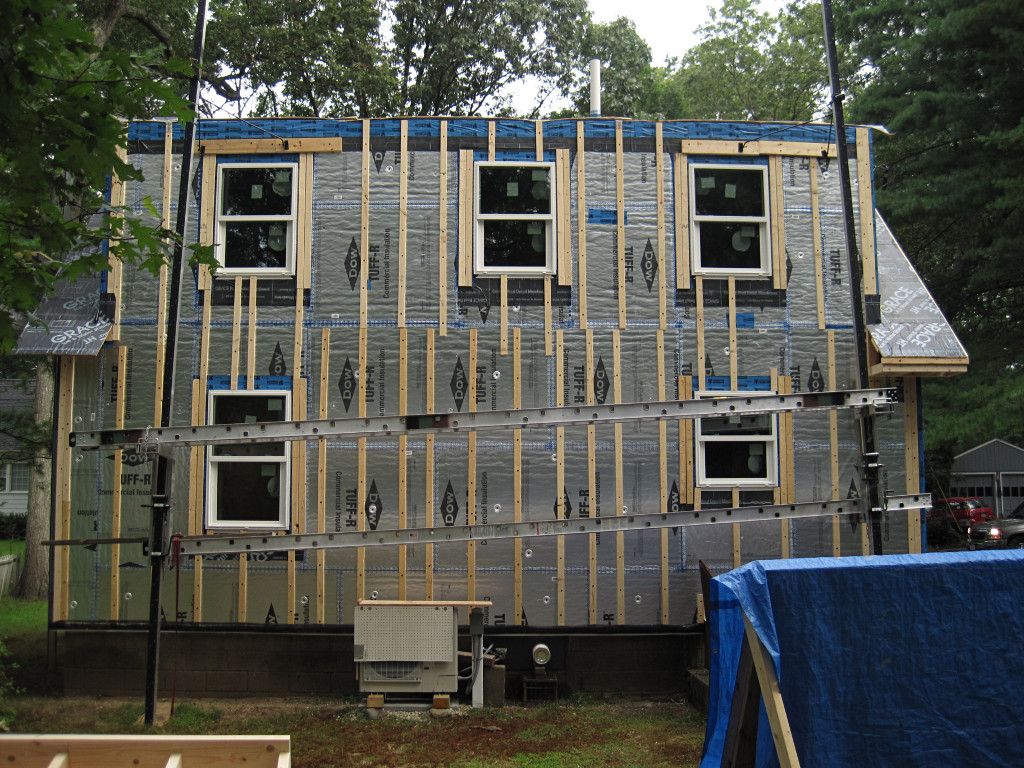
This also is an okay general shot of the back of the place along with the completed storm door on the side. A *very* close look shows an ever-so-slight mismatch in the top of the storm frame; that's just how it went onto the trim and the side frame pieces; nothing I could really do about it. It seals properly and looks fine unless you're really giving it the critical eyeball. The two wing-wall pieces of roof weren't going to get gutters; I had already laid down little pebble beds to catch and dissipate runoff from their ends and I wasn't worried about the volume of water likely to come down them. |

|
First job was to put the downspout assemblies together. He brought the fat, high-capacity 3 x 4 inch stuff, none of the weenie 2 x 3 most homes have. This wasn't seamless, it was sections that got zip-screwed together. The downspout mounting brackets were attached to the house at this point, which was a little interesting in the back as the strapping behind where he wanted to put the run wasn't quite in the right place. I had to remind him about how to work with the air-gap rainscreen. Perhaps I should have shown him one of my strapping pictures so he could see the actual path of wood he was trying to find. |

|
The set for the back would obviously be very long, and would go onto the house as a single unit. |

|
Next he started extruding the gutter sections, building details like
end caps and downspout connections as it emerged.
The forming machine is pretty nifty, albeit simple in principle -- basically a rolling mill that is set up for exactly one shape, the 5-inch K-style gutter. |

|
The end cap got crimped on and then sealed with ordinary acetic-acid-cure silicone caulk, but the downspout nipple got some special stuff whose name I didn't catch but is specifically made for gutters -- it bonds to the aluminum better than other materials, and here also forms a smooth ramp up the little lip of the fitting so crud is less likely to dam up at that point. |

|

|
| He formed and assembled both pieces while out here. With the roller stands ready to receive the piece as it came out he didn't even need me to hold or guide anything. Once formed, the stuff is pretty strong and self-supporting. While the outside is "trim white" to match what's on the roofline of just about any house, the inside looks like a type of clearcoat and possibly over some sort of anodized treatment. | |

|
Next was to dump a big handful of hangar brackets into each gutter and
clip them in at roughly 16-inch spacing. These are the "concealed"
brackets that long since replaced the big ol' spikes with visible heads
on the outside; they make for fast installation with their own screws
already pre-inserted and ready to just run in.
I pointed out that he had a nice meaty 2 x 6 to attach to under the trim metal, which was great for him and would allow plenty of room for establishing a good pitch over the 30-foot or so runs. |

|
The assembled piece for the rear headed off through the yard. |

|
Here's where he actually wanted a little help from me. From the middle he couldn't tell where the ends were at all, so he held it up and had me run back and forth to look at both ends and guide him until the piece was centered. From there he drove a couple of screws in the middle, and the piece could balance there indefinitely while he moved ladders around to start fastening in the rest. |

|
Which involved plenty of the expected sketchy reaches off the ladder to
accomplish, of course. I can't imagine anybody trying to do this without
modern screw-guns unless they were a hardcore old-school masochist, but
then they'd probably be using steel nails and wondering why the whole
system fell apart in ten years.
But come to think of it, I don't actually know what the bracket screws are made from. I would assume aluminum, given everything around them... |

|
A ladders' eye view of the installation, before everything was buttoned down. Both here on the back and in the front it turned out that the roof panels were going to deliver water just about perfectly into the gutters. Here on the shed the panel line continued to just barely above the lip of the gutter, which might make eventual snow shedding easier; the angle was steeper on the front but that was fine as water might be rolling a little faster down the front and it would zip right into the middle of that gutter. |
|
Yes, there is a very slight dip at the far corner of the overhang,
probably from that warped plywood and the framing piece that had to
be wrestled into place over there. That actually helped establish
proper pitch on the gutter as it got over to that point, so it's all
good. You'd never notice that unless you were looking for it.
Nothing fancier than a small bullet level was needed to establish overall
pitch toward the downspouts; I had envisioned complex machinations with
a water-tube level held up at either end but it's much easier than that.
What isn't shown is that both runs of gutters got leaf-guard screen covers, I think one of several different types made by Englert although I can't find the specific type on their website. There's a shot of it later on, when I pulled some of it to experiment with different types of gutter-guard. | |

|
Last thing was to attach the downspouts, and I had given the guy a pretty
clear idea about where I wanted them to drain -- generously far away from
the foundation. For the very short term I stuck a couple of pieces of
slate under the ends as splash blocks, but I had a far better solution
in the pipeline that I started a couple of days later.
This is the slightly lower side of the property and away from the driveway, and the ground slopes gently away from the wall but not enough to shoot water into the neighbor's yard. The subsoil is fairly loose and sandy over here. It's almost the perfect drainage scenario. |

|
My idea was to construct the equivalent of splash blocks with a layer of
stone, but to go it one better and actually make small drywell-like pits
to give them some local absorption capacity before spilling onto grade level.
And I had all these random rocks that I'd dug up all over the property,
that weren't otherwise going to be used. It was time to go play in the
dirt again, which I found I was rather enjoying.
As I got deeper into this particular pit I met up with one really large rock in the way, but I decided to leave it in as part of the system. Basically each pit, maybe only a foot and a half deep, got filled with the largest rocks on the bottom, and working downward in size toward the top. This would ensure plenty of space and thus absorption area into the dirt below around the bottom of the pit, and more space to accomodate any organic muck that happened to filter down. |
| While I had pulled out and cleaned off lots of mid-size rocks from various other digs around the place such as the well-decoration and the hutch post pits and under the side stoop, ultimately I didn't have enough rocks. And this is New England, we should certainly have plenty of rocks. But to finish the pits I actually had to go hit the local hardware store and *buy* bags of rocks. Not that this was really a problem, as they're all of four bucks a bag, but it was fun to make an ersatz big deal about not having enough rocks. I even got an extra bag for free after offering to pick up the spill from the bottom of the stock that had broken open and scattered on the pallet at the store, and that quantity of "river pebbles", as they refer to the 1 to 2 inch size I needed, was enough to nicely finish both drainage pits to just below the grade of the surrounding ground. | |

|
I actually had a looming time deadline on finishing the drainage pits.
Hurricane Sandy bore down on the northeast and brought the perfect
opportunity to brute-test the entire system, gutters/downspouts and my pits
all together. Here's the front pit
in one of the heavier storm rainfalls doing exactly the right thing: with
a large flow it gradually filled up, and then just gently overflowed at
the downhill edge and puddled a little way out onto the surrounding lawn
where it simply soaked right in. So I was pretty happy seeing my concept
for erosion protection and drainage-with-overflow work just fine in one
of the biggest storms the area had seen in a long time.
I had also found an entertaining tentative use for the two chimney-flue sections I still had kicking around -- stabilizers for the downspout ends. They looked a little klunky but would protect the relatively delicate pieces quite well. My jury was still out on whether I'd keep this arrangement or replace the flue sections with something smaller. |
|
Sandy actually didn't drop that much rain overall, but she brought far and
away the highest winds I've ever seen around here and it was pretty
downright scary for a while with everything whipping around. Fortunately
all the trees remained upright and didn't fall on my nice new roof.
Again, the downside of all that complex structure up there is that in
the event of damage, it's far more of a bitch to fix than generic to-code
construction.
Part of my storm prep had also been to compact that remaining pile of polyiso foam pieces in the backyard and tie the whole pile down so pieces wouldn't start blowing away. They would have gone everywhere if I hadn't done that. I was really glad I'd gotten the storm door onto the side, too. Sandy came straight from the east for most of the time, and that whole side of the house was *covered* with crap afterward as the overhangs were rendered largely irrelevant. The nice well-sealed storm door bore the brunt of the sideways wind and rain and kept the main door completely dry, which would have been a soaking mess otherwise. It also let me spot a couple of small water leaks in the storm-door system that got caulked up later.
|

|
The other big height-of-storm test was whether the roof was finally draining
right, and what was happening with the brandy-new gutters. The heavy drip
onto the A/C hutch roof had ceased as expected, but with all the sideways
rain blast from the storm I was expecting any type of wackiness.
Raindrops happen to make nice retroreflectors when they're hanging on something ready to fall, and with the flashlight right next to the camera at night it was easy to see that even during the big storm, nothing bad was happening in terms of where water was going. The drops on the bottom of the gutter were simply from rain that had just tagged the outer lip and then run down the outside; none of that was about to head farther inward. |
|
At this point I figured all the random drainage issues had been fixed,
even if the supporting structure underneath wasn't perfect. *IF* the
various re-sealing along the ridgeline stayed intact, the installation
of Tri-flex [and/or that lame substitute tarpaper on the shed] was all
good under the roof panels and over the drip-edge, the ridge cap not
leaving any water paths farther in, and all the layers of
Grace underneath correctly patched and sealed, I should be in good shape
for the foreseeable future.
It just still mildly sucked knowing there were several *preventable* issues
under there that I'd just have to live with. I would watch the siding for
any signs of mis-routed water, and a peek up inside the overhang soffit
every so often couldn't hurt now that I knew how to zip it open.
Ironically, contracting companies spout lots of stuff about "durable structures", and then only offer a one-year warranty on their work. Knowing what I know now, that speaks volumes. The only remaining minor problem was the fact that water falling down that very long downspout in the back was *loud*, and right outside where I sleep. I began thinking that water with that much velocity could eventually start eroding the downspout from the inside, and started wondering what I could do about that. Reroute the whole thing with an extra bend or two? A longer-radius elbow at the bottom? A bit of searching on what parts might help turned up something at Gutterworks called a downspout silencer, which seemed like an easy first thing to try. The picture there didn't show every detail but the more I thought about it, buying something like this seemed silly when I could probably just construct my own equivalent. |

|
I had parts that would likely do. The silencer was pretty clearly some
kind of absorptive but permeable material, perhaps sort of like
ScotchBrite -- or, in fact, this floor-polisher pad I happened to have
kicking around. All it needed was a little support to hold a strip of it
in the right place, easily whacked out of yet more sheet aluminum.
Why the F did I have floor-polisher pads, without owning a floor polisher? No idea, they were more of the random curious detritus left to me by the previous owner of the house twenty-plus years ago and I never threw them away. This entertaining re-use is why good ol' New England frugality says to save that kind of stuff, even if it borders on hoarding. |

|
A zero-fastener approach was probably best, relying on little bent tabs to retain the sponge piece. |

|
Development and construction of the solution took less time than I thought it would, and soon I was back outside ready to drop this little creation into place. A simple bent-over tab of metal would retain it at the top of the B-style elbow. |

|
This is what falling water would henceforth hit: a nice absorptive surface
to damp the impact, and into a porous layer it could just flow through or
over and keep going toward the rock-pit.
Inserting this and buttoning the whole downspout back up was completely trivial, and it profoundly improved matters with regard to noise. Not only does it absorb impact of the drip, it adds an extra layer of aluminum to protect the inner surface of the downspout elbow. |
|
I didn't bother doing likewise on the front downspout, as it's half the
fall distance and I couldn't really hear anything from it. Probably
nowhere enough impact energy to worry about -- emm-vee-squared, remember.
And water falling into an A-style elbow instead is perhaps spread over a
slightly larger area.
Another thing I thought about while looking at this was eventually burying an impermeable barrier layer under this area pitched away from the foundation wall, or an "underground gutter" as it's often called. If the downspout ever got damaged it would dump the whole shed roof's worth of water right here next to the foundation, hardly a good scenario even with the bit of earth berming up against the wall I'd already done. A subterranean sheet of something would at least encourage absorption to happen farther out. One night in the midst of these fixes I had a pretty bizarre dream about drainage in general, where somehow the entire yard behind the house had turned into a huge riprap-lined retention pond and there was a complex maze of pipes, water deflectors and pumps attached to the back of the house. Like "rainwater management" gone horribly over the top. Presumably I had designed and/or built all of that, but in the dream I had no idea what any of it really did or why it was even there and was having all kinds of angst about long-term maintenance. Hopefully the reality would stay far simpler. | |
HVAC integration
Over time I had finally clarified what functions and cross-connections
I wanted to add to the HVAC system, and had determined which ones were
feasible and which weren't. I needed a few external components and
accessible interconnect points, and figured it would be easiest to tie it
all together in one place. In particular, I needed to implement all of
|

|
The HRV override in particular was problematic because it would need a relay in between. The Daikin enables a 24VAC "thermo" output when it is actively cooling, but the HRV's available "dehum" override input is designed for just a dry contact and provides its own bias. Just banging those two together would likely be bad. After reminding myself that relays for AC vs. DC coil operation *are* differently designed I went out and bought one, instead of trying to mismatch something out of the junkbox that might buzz and/or fail at an inopportune time. Because of needing a relay, a couple of switches and lights, and a place to connect runs between different pieces of gear, the concept of an "integration box" to mount outside the air-handler developed. Everything would tie into the easy-to-work-with terminal block. |

|

|
|
The project went together fairly neatly, leaving plenty of room to route
wiring in and connect it. A sensible place to mount the box was up near
the rest of the switches and wiring for the air handler, but attached to
the HRV collector box and *not* the AHU ductwork since the latter does
get a little wet in summer. A nice big fat red LED on the end lights
when the "toaster" control line turns on, not that it would do any good
producing heat if the "AUX" heater power switch is off anyway. The point
of that is to know when either a>the system *tries* to use the heat
strips on its own or b> an external thermostat calls for heat.
The white molex would eventually receive wiring from a limit switch in the condensate pump tray, but a bit more work was needed to actually add one before this could be finished. It would kick the Daikin's "forced off" input, which upon closure simply behaves as though someone used the controller button upstairs to shut the system down. | |

|
The AHU end of all this also worked out nicely, with a single multiconductor cable breaking out near the terminal blocks and the heater relay. My leads to the heater relay [actually a "therm-o-disc" time-delay contactor] pushed right onto the double-tab quick connects and everything else found its way to a terminal block. Exact connections were important, as each function's terminal pair has what I arbitrarily named an "R" side and a "C" side from the 24V power supply and mixing them up would risk blowing a little not-easy-to-access fuse on the control board. Here's a wiring diagram of the whole setup, partially for my own reference but also instructive to anyone else looking to enhance the functionality of this particular air handler or work around its deficiencies. I even tried to make the wire colors vaguely match those found in typical thermostat connections. |

|
And the biggest, most grandiose and egregious almost-showstopping deficiency is the fact that the system won't run itself on emergency heat [e.g. only using the toaster] in a situation that would call for it. Thus, to set up for doing my heat-load measurements I had to resurrect my old thermostat from the oil system and mount it up semi-temporarily across the hall from the Daikin controller, at the same height so it would sense room temp at roughly the same location. Rather than mess with the wall I opted to lean a scrap of ply up next to the basement door and attach to that. Tucked behind the bottom of the board was a little circuit using the switched 24VAC to briefly beep a Sonalert in different characteristic ways depending on if a transition was on or off, and the control wire simply went under the door and down to the system. Usage would be to kill the data line to outside, run the AHU steadily on low fan, and let the t-stat heat the house the expensive way for as long as it took to collect the numbers. In spite of Daikin making it stupidly difficult for the experimenter, I was finally ready to go on this and all I needed now was consistently cold weather. |
_H* 121228