My Leakin' Daikin: an ongoing diagnostic adventure

  Heat pumps are great technology, until they aren't, when something goes wrong.  Then it can turn into a deep dive into technical diagnosis and frustrating guesswork, often chasing subtle and hard-to-find problems.  The Daikin was pretty solid for six years after installation, other than the waterlogged thermistor problem.  Then, just heading into the next heating season, one October day I noticed that it seemed to be running for a really long time and not managing to make much useful heat.  The superficial "diagnostics" I could get from the controller told me that the overall output from the indoor coil was only 80 degrees or so, not up to the usual 105 or 110 where it usually runs.  That might have eventually gotten the house somewhat warmer, but at the expense of how much time?  Clearly, something wasn't right.

The "service mode" on the control panel also showed the outdoor evaporation temperature wandering around at a fairly ridiculous low level, like -20F in maybe a 40 degree day.  Normally the system runs the outdoor coil about 10 - 15 degrees under ambient, which is enough to pick up heat from the outside air and bring it inside.  This is a little nonintuitively puzzling -- if the outdoor coil is so much colder than the air around it, why wouldn't it be picking up *plenty* of heat to transfer in?

Well, the properties of refrigerants aren't that simple, and the numbers I was reading were actually quite misleading.  To transfer heat efficiently, refrigerant has to change state evenly across the entire area of an exchange device, aka a coil with fins on it.  If liquid refrigerant flow is low and it tries to expand into a given volume of piping, it can all flash to gas immediately and then spend the rest of the journey through the exchanger fairly uselessly at ambient temperature, picking up almost nothing.  So it might get really cold early in the process, but there just isn't enough mass of it flowing to maintain that state-change process through the entire length of piping.
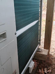
Unable to expand through full coil capacity: the 'ice finger' That's hard to explain without a good understanding of how refrigerants work, but here's the externally viewable symptom: the "icy finger" of super-cold that lasts for about one pass along the coil's width, and then is all boiled off to vapor and doesn't cool any of the rest.  It may have to be taken somewhat on faith, but this is a classic symptom of low refrigerant charge in many types of systems.

In other words, enough of the "magic juice" had leaked out, leaving the system valiantly struggling to perform but just not able to deliver.  I eventually learned to recognize the "ridiculous superheat" as the definitive symptom of needing more refrigerant, and after a couple of expensive technician visits involving weighing charges in and out, I knew about how far down it was when the symptoms started.


  The first time this problem began, though, I had *no* idea what was going on.  Was the compressor shot?  The reversing valve internally leaking?  An expansion valve not opening to the correct point?  All kinds of guesswork flooded through my head because I didn't yet realize what the real problem was.  Parts of the system were still a deep mystery, despite having all the service documentation from Daikin on hand.  Whatever the cause, I figured that it would ultimately need professional eyeballs and tools.  This was all pre-pandemic, so the first go-round or two of trying to call a contractor weren't quite as terrifying and frustrating as later on.

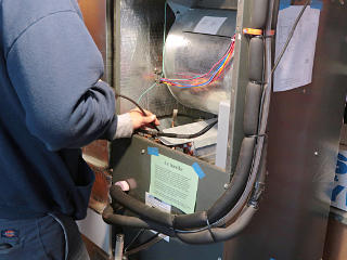
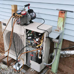
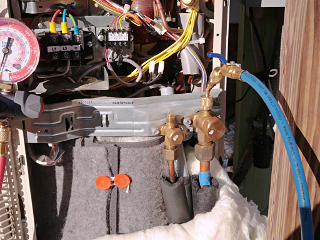
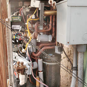
All covers off the piping area To see just how much of a pain in the ass any pipe work on the system might be and to look around the innards for anything untoward, I took all the covers off the relevant end of the unit.  I could already see that something like changing out a reversing valve would be tricky if not downright impossible, given the work space and the short runs of pipe from it.  I got to wondering how often units like this actually get *repaired*, or just junked and replaced with an updated one.

  Anyway, with nothing obvious *I* could find wrong, it was clearly time to call the professionals.  And here's where we start condensing [ha!] about three years' worth of story into one general rundown on what the diagnostic and recharge process entails.  And after getting into some serious deep technical weeds, my eventual elegant, cost-saving solution.

So we start with Technician #1, who seemed fairly impressed and amused by the things I already knew about my own system.  During his visit he took some phone pictures of my hacks and the whiteboard diagrams on my kitchen wall, "for the guys".


Bubble-testing the flares The common assumption was that the problem was simply a slow leak and a low charge as a result.  And some usual first-line suspects are lineset flare fittings.  Sniffing around them outdoors with breeze going past isn't a particularly reliable test unless it's a larger leak, so the next step is to bubble-test everything and look for some point foaming up, even a little bit.  The bubble goop sold to HVAC technicians isn't just soapy water, it's a viscous sticky mix of high surface-tension components to really support stable bubble formation.  For the most part it's still water-soluble, so it can be rinsed off with a wet rag after you've gooped everything up with a spray bottle.

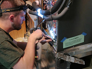
Sniffing around the air handler Sniffing deeper into the air handler
The next suspect on the list is often the indoor coil, which runs wet all summer and frequently develops what's called "formicary" corrosion, aka groups of microscopic pinholes through the copper tubing or at braze joints.  The term comes loosely from the internal topology of anthills.  In anything except the newest types of all-aluminum coils, we have three dissimilar metals in intimate contact -- copper piping, aluminum fins, and steel frame pieces.  Add water, and we have a galvanic witches' brew indeed.  A similar situation exists in the outdoor coil but its periods of dampness are generally shorter, and it sits outside with plenty of air circulation even when it's not active.

The tech *almost* thought he got a hint of detection near the bottom of the coil, but after taking the lower front cover off he still couldn't find anything solid.  It did provide another good look at the high-side thermistor, where I could confirm that its wiring enters from below and is thus less likely to get water seeping into the capsule.


Sniffing the underside of the coil I pointed out that I'd installed the plenum access hatch for a reason, so he did due-diligence probing all around the underside as far as he could reach.  Still nothing.

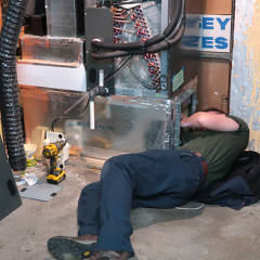
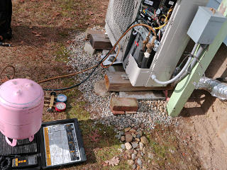
Recovery setup The system still needed the proper charge, and the only given "proper" way to ensure that is to pull the entire existing charge and replace it with the spec amount weighed in.  So step 1 is recovery.  I reminded the guy about the all-valves-open service setting these units have, which ensures that recovery vacuum easily reaches all parts of the system.  We also agreed that weighing *out* whatever charge was left inside it would be a good indicator of how much had been lost.  This knowledge became important later.

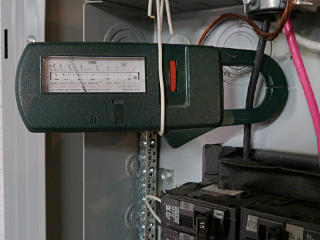
Recovery pump current The recovery unit was running from the auxiliary outlet in the disconnect box, so I could see the current it was drawing.  Its internal compressor had to work "uphill" against the recovery tank pressure, so it was pulling a nontrivial 700 watts or so.

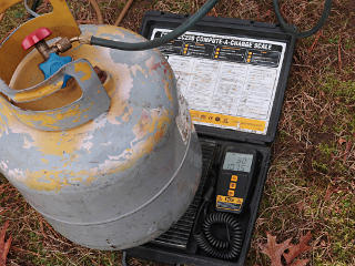
Weighing recovered refrigerant out The numbers here don't really show it, but the remaining amount of refrigerant turned out to be just shy of 4 pounds.  Out of 7.5 pounds nominal, so the system had lost nearly half of its rated charge before becoming unable to compensate for the loss.  Given the lack of obvious leaks, that must have escaped over quite a long time, while the system was still functioning properly.  When you compare that against older "critical charge" systems, the computer system control with sensor feedback reflects an impressive ability to adapt to suboptimal conditions and still run efficiently.
Technician #1 finished up fairly normally, and while the visit left me over $800 poorer, the system was back to rights and stayed properly functional over most of that winter.  But by March it was starting to wheeze again, and the underperformance and return of the "icy finger" along the coil told me that I evidently needed another expensive truck roll.

    Dammit.

This was already getting super-old.


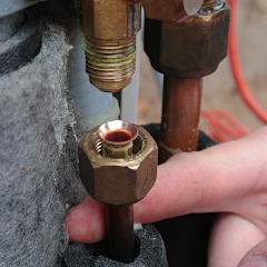
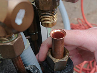
Flare inspection: liquid Flare inspection: suction
Technician #2 was a different guy from the same company as before, and for one of the most bizarre reasons I'd ever encountered.  Apparently the first fellow they sent out, who seemed to appreciate the geek factor of my system and my understanding, had suddenly died of a brain aneurism about a month after that visit.  Perfectly healthy otherwise, competent and contented in his job ... and then out of nowhere, blammo, just never woke up one day.  You just never know when something like that can happen.

That was unfortunate in many ways, but one of those was that I had to basically start over and train up another guy on what my system consisted of and what had gone before with it.  He came up to speed soon enough, and along with more fruitless leak-sniffing, we agreed to try a couple more things to proactively seal the system better.  With it once again emptied of about the same remaining amount of refrigerant as before, I suggested opening the flare fittings for a good look and possible improved sealing with a bit of lubricant on reassembly.

Now, these were the same flares that had been sketchily installed in the first place, the larger of which was visibly leaking the day after and all the installer did on the callback was crank the nuts down tighter.  These had never been disassembled since, on the assumption that if they weren't leaking in any obvious way, they were best left alone.  But Technician #2 seemed confident that because they were always suspect, they could be opened, inspected, and reassembled in a more leakproof way by applying the Nylog that the original guy should have used in the first place.

The surfaces actally looked fairly good, so he spun a little Nylog around the threads and the back of the flares and buttoned things up again.  He resisted the concept of putting anything on the *mating* surfaces, even though Nylog is supposed to be safe for systems if a little bit of it gets into where the refrigerant circulates.  It's basically a super-thick polyolester oil.  Still, color me skeptical of the sealing ability of a raw metal-to-metal junction.

What's ironic is that now they actually make crush seals for flare connections now, for exactly this issue, but the guy didn't offer to install those at the time or possibly even didn't know about them yet.  Next time these get opened, if ever, maybe that's something to do as well.


Vaccuming down the system Weighing in new charge
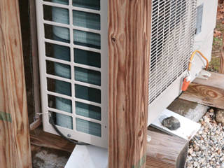
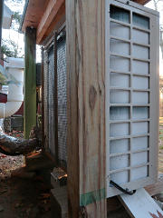
For this visit, I removed the hutch rooflet and front posts, to give him plenty of room to work in case we needed to get farther into things.  It wasn't really necessary; there's ample room to access the ports with the front post still present.

We didn't pressure-test, but he figured another evacuate-and-hold cycle would be enough of a reasonable leak test.  Naturally this also requires the test hoses to be in good shape too, as they become part of the evacuated system as long as they're hooked up.  There was no obvious pressure rise over a reasonable time, so he went ahead with refilling.  I showed him my charge calculations based on the spec per foot of lineset and indoor coil addition factor, and he actually overshot a little and put closer to 8 pounds in the system.  It actually seems quite happy with that much in it; there's a monster accumulator on the suction side that can buffer a lot of excess.


  Now, a vacuum-rise check has an inherent flaw, that when piping is evacuated, hairline cracks at joints can actually get pulled together and self-seal as opposed to being forced open wider under high internal pressure.  On the heating cycle, the entire lineset and indoor coil is part of the *high* pressure side, increasing the likelihood that pressure-variant leak points might actually leak more under those conditions but not others.  I had never seen any issues with cooling; the issues seemed to only show up once the system kicked back to heating mode and put high pressure in the whole vapor side and indoor coil.  This made me continue to suspect a problem on the indoor side.

To facilitate longer-term diagnostics, the guy suggested putting some fluorescent dye in the system which might help locate a tiny leak over time.  He assured me that it wouldn't harm the system at all and wasn't any kind of leak *sealer*, which is still the subject of raging debate across the industry.  A simple tracer visible under UV light might give a better chance of letting me eventually find the leak, so I was on board with that.  He understood that I would be perfectly comfortable continuing with my own diagnostics, and that an appropriate light source would be inexpensive.


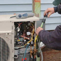
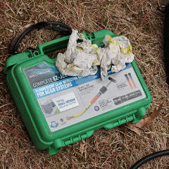
Tracer dye injection Spectrodyne dye kit
Here's how the dye kit works.  This is forcible injection over system pressure with a little plunger pump, and some of the later kits simply use high-side pressure to push a quantity of dye into the low side.  Whichever it is, it is generally done with the system running, to immediately mix the dye through the refrigerant and distribute it.  The plunger method can get a little messy, as not all the dye leaves the injector and when the fitting is unscrewed from the access port, some if it can spew back onto whatever's nearby.  Which, of course, it did here...

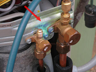
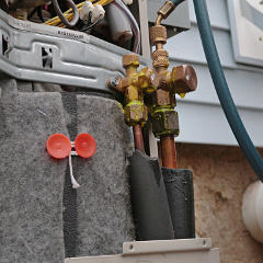
A bit of dye splash So already, there was a bit of dye showing on and around the flare fittings and ports, potentially misleading later observation.  I wiped it all down as much as I could, but the stuff is *intended* to stain metal surfaces.  The spread pattern from an actual leak looks a little different, and when the dye combines with a little refrigerant oil the mix can "creep" along metal surfaces in a somewhat characteristic way.

Nylog was also applied to the access-port threads and flanges as they got buttoned up again, to make sure the caps were sealing right.  Those are another direct metal-to-metal contact in this case; there are no O-rings inside the caps.  Again, this seems like an inherently flawed idea, as the tiniest scratch in one of those surfaces could easily leave a leak path.


  A few days later I had an appropriate 360 nm UV flashlight in hand, and was now equipped to do as much leak-chasing as I cared to.  But the Nylog job must have helped quite a bit -- for the rest of that heating season and about a year and a half further on, the system performed as intended.  That took us well into the pandemic, when the last thing anyone wanted to worry about was HVAC problems, and everyone was in lockdown and terrified over the idea of a contractor having to work in someone else's house.  I made it through the token cooling/dehumidification period over the summer of 2020, and then as I swung back into heating that Fall and was starting to feel a little more confident that the leak might actually be gone, guess what.

    *Argh*.

Still with the Covid-driven apparent impossibility of finding someone to come out and do the $800 "refill dance", in despair I simply shut off the outdoor unit and started heating on the 3 kW "backup" resistance element.  Good thing I had done the secondary thermostat integration to let that work independently, because now I really needed it as "emergency heat".  While that is *just* enough to heat the house through most of the winter, it is decidedly the expensive way to do it, as there's no benefit from the COP of the heat pump *and* it has to run longer to produce the same overall BTUs inside.  With the refrigerant side of the picture out of commission again, I was almost resigned to having to go through the entire winter on the resistance coil and who knew when I'd be able to ever get the heat pump fixed.

And the kicker was that I *still* couldn't find any evidence of an identifiable leak point, even scanning all over everything with the UV light and trying to sniff key points with an ancient leak-finder I'd had for years and filter out all the false alarms.  That was only really a gas density detector, not specific for refrigerants, and would start indicating on just about anything including dust in the air.  At one point I slit into the lineset insulation at a couple of points to see if I could detect anything along the piping, and the wheezy old sniffer started alarming on the *outgas* from the cut foam cells. 

By now I knew that all the system really needed short-term was a simple top-up of R410A, about three pounds worth.  But that wasn't something I could just hop down to the hardware store and buy.  Sale of refrigerants is quite restricted, to certified industry professionals, and a bit of specialized gear is also needed to fill a system.  One of my nearish neighbors works in the HVAC industry and has his "ticket" to legally work on this stuff, and at some point we got to talking about my system.  He offered to wander over and take a quick look, and after another couple of superficial and negative sniff and bubble tests, he came up with a couple of useful ideas on how to proceed.

One was that he could bring his gear over and add the three or so pounds of refrigerant needed, which could hold me over for a while if the leak rate remained steadily low.  This is called a "gas-n-go", and while it isn't the most environmentally friendly approach, is done all the time in the industry.  For small systems, escape of a pound or two per year of HFC refrigerants isn't considered so big a deal -- especially compared to some of the allowable leakage from large industrial systems.  The right answer, of course, is to fix the leak, but if it's proving just about impossible to *find*, we run into the limits of practicality and labor cost.  We geeked a bit about all of this, and he seemed somewhat impressed that I knew what I did about the system and what to add and get the system charge back to nominal.


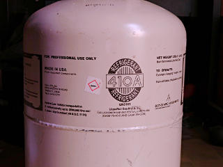
R410A tank details while pre-warming Since we were already into late Fall by then the weather outside was a bit cooler, so one evening he came by and fetched a tank of "juice" out of his truck so it could sit inside my kitchen for the night and stay warm.  The next morning we'd do the top-up, and the pressure in the jug would be substantially over that of the system to make it easier.

Since I'd never examined one of these tanks carefully, it seemed worth recording the text that they generally have on them.  The pressure inside is a direct function of temperature, and somewhat counter-intuitively, at higher temperature/pressure more of the refrigerant is in liquid phase and thus incompressible, which is why storage of a full one at too high a temperature is super-dangerous.


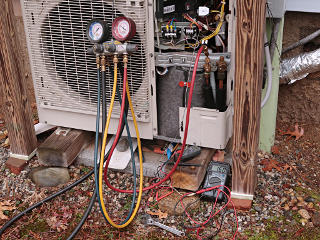
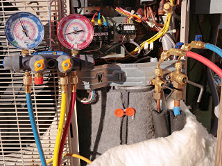
Neighborhood buddy's gauges on, plus voltmeter hack In the morning I went out and hooked up my voltmeter pressure-read hack and a couple of VOMs, and later the neighborhood buddy came by with his manifold gauges slung over his shoulder and hooked up to the high-side port.  Since all we would be doing was adding liquid refrigerant from the bottle with the system not running, this made sense.  He left me to slowly valve in the "juice" and watch the scale, while he wandered off to attend to some real-day-job business.  The warmer jug easily overcame the quiescent system pressure, and after about three and a half pounds I stopped and we informally settled up -- a token bit of coin exchanged hands for this, because R410A is not cheap.  So I was up and limping once again with more or less normal system behavior.

Normal wide bands of frost Really frosted up on a cool but humid day
"Normal" is easily visible during days of appropriate temperature and humidity, where the outdoor coil goes below 32F and water vapor starts condensing on it and freezing.  As the evaporation stabilizes, frost progressively builds from the liquid end of the coil toward the vapor end -- but over a much longer distance than the "icy finger".  This coil is split into two halves, top and bottom, and each section is piped in kind of an odd order.  The first few passes are grouped at the bottom but then for some reason the end loops jump the order up a bit, then back down, visible in the initial pattern of ice-up seen on the left here.  It may have something to do with optimizing for the airflow, no idea.  Once the entire coil is properly cold and has been running for a while, it can and should frost completely up -- except for a tiny sliver at the top of each half, where it's back to all gas state at ambient temperature.  That's the correct touch of superheat we're looking for.

One might ask, how does any air get through once it's that frosted up?  Well, just the turbulence of the fan straining to pull air through can still let the coil extract more heat from the air, but once the sensors start detecting that there's too *little* superheat, a defrost cycle is done.  The system actually isn't that smart about it, and likely includes some simple blind timing into that determination -- on dry days where there's no frosting at all, it still does defrosts every so often even when there's no need for it.  I can basically "hear" how blocked up the coil is by the louder roaring that the fan makes, without looking out the window. 


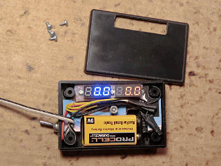
Convenient voltmeter box for pressure measurements At some point in the midst of all this I decided to construct a little box to make the "voltmeter pressure-read hack" more convenient.  Two little tiny digital meters, in red and blue, a 9 volt battery, and my original connection cable.  This and my P/T voltage chart makes high and low pressure reads fairly easy, and those are always measured at the compressor, independent of the reversing valve.
It was after putting this together and thinking about it a bit, that I finally realized that the "thermistor" figures that the wall controller shows me about the outdoor unit are actually doing the same thing: equating the voltages from the same sensors to what the temperature *would* be for R410A in saturation at the given pressure.  This is invariant, and one of the most magic properties of refrigerants -- whether you have two ounces or twenty pounds of liquid in an R410A jug, its pressure will be exactly the same at a given temperature.  Watching the meters during the system's "struggling" phase showed the low-side voltage dipping fairly drastically down, to like the equivalent of 50 PSI or thereabouts.  Suddenly the "ridiculous superheat" scenario became clear, as the "temp" reading of -20F simply equated to very low suction pressure as insufficient refrigerant was coming through the expansion valve.

Oddly, even in that pathological under-fed state the suction pressure never reached the cutoff point and the system never threw an error, it would just keep trying even if it was just wasting energy for very little heat by then.


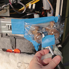
Trying to contain potential leak area Efforts to find the leak continued.  My ancient gas-density sniffer *would* detect R410A in enough concentration relative to air, so I constructed a sort of bag around the flares and access ports with a small hole for the probe, to see if anything would build up inside without dissipating in the breeze.  Still nothing; it was hard to get this decently sealed just due to the geometry of the fittings and bracket, so it wasn't really a good test. I started thinking seriously about needing better tools.

  Another thing my neighborhood buddy had mentioned was the possibility of becoming certified to work with refrigerants, so that supply houses would be willing to sell them to me and maybe treat me with a little more respect than is afforded "homeowners".  He seemed impressed by what I knew already, and said that the tests weren't that hard after a bit of study-up, and that's all that was required rather than having to be a full-blown "licensed contractor" on paper.  This would allow me to do my own top-ups, and given the observed leak rate, I figured one 25-pound jug of R410A could last me the next 5 or 6 years if things stayed as they had been over the last three.

This idea took root and grew, and along with possibly getting myself EPA 608 certified, as it's known, I could already buy HVAC tools on Amazon without even having that status.  After observing my various service visits and a few Youtubes I knew I could easily and safely handle this stuff, so why not?  If a bit more money and passing a test involving some science were all that stood in the way, it was a project well worth tackling.  I started making a list of what I'd need as permanently owned tools to work on the system, and easily found a lot of good EPA study guides all over the internet for free.  While the neighborhood guy had recommended the two or three evening training course that he'd taken over at S.G.Torrice, it became clear that I could just learn this stuff on my own and only bring in an external agency to proctor the test when I was ready for it.

And to hasten this process along, this latest top-up only lasted about a month before the system was wheezing again and giving me "the finger" of premature evaporation.  Either the leak had gotten worse, or my neighborhood buddy had done something wrong when he unhooked and closed up the fittings again.  I didn't feel right about pestering him to keep coming by with his pink bottles of salvation, and at this point, *fuck* if I was going to keep paying for $800 "professional" truck rolls.  I was determined now: I'd go ahead and get myself able to pursue this whole mess on my own, and began working on several fronts to make that happen.


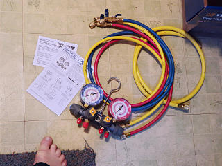
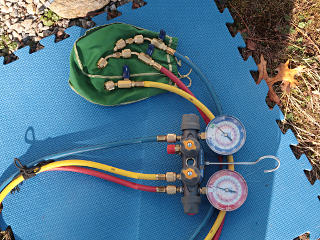
New Yellow Jacket gauge set Soon enough, new fun toys started showing up on my doorstep.  The centerpiece was a genuine Yellow Jacket gauge set with hoses and low-loss ball valve fittings and 5/16" adapters for my system -- none of the offshore garbage that also floods Amazon, I went for the industry-leading quality here.  I didn't need the fancy electronic versions, just a basic pair of mechanical gauges, and ports for filling and evacuation.  Basically enough to take readings and hook up to the system and a tank.

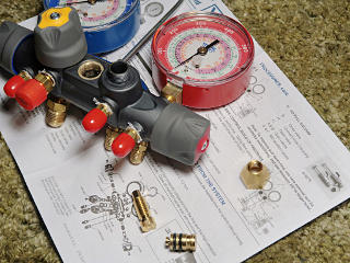
Manifold valve disassembly/inspect Still a little unclear of the routing and function of the manifold's valves, I took one apart for a look-see.  It's interesting how the actuation screw couples to the plunger but doesn't spin it, presumably decreasing gasket wear-out.  I discovered later that the valve handles feel very different when they're under pressure or not, and having some lube on the actuator threads is fairly important to avoid metal-to-metal spalling.  The next call was to Yellow Jacket to ask what they'd recommend to re-lubricate the valve parts and O-rings, and the answer was generic white lithium grease.

Basically, every valve simply opens its port into the common chamber in the middle.  The gauges connect directly to the respective high and low side hoses.


Nice bag to keep hose fittings clean Taking a page from how we handle traditional sound snakes, I add a "pig bag" to my kit, to keep all the fittings nice and clean and off the ground.  Not letting foreign material get into those or the system is super-important, and if there's oil on some of the parts they will definitely attract dirt.

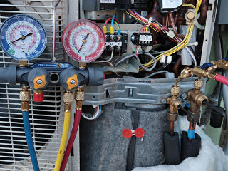
Schrader caps off [with leftover dye] When the gauge set arrived I didn't have the certification or a "jug of juice" available yet, but as the manifold and hoses were full of air, I needed a source of R410A to purge them out and get the kit ready for real use.  The available path was to draw a tiny bit off the system itself, just to practice proper purging procedure with minimal loss anyway.  With being back to resistance-heating mode *again* for the moment, I had little to lose here, so now it was play time.  I set up in front of the outdoor unit and opened up the access port caps, revealing the Schrader valves inside that the hose fittings would depress and let me see system pressures.

At the moment of cracking those caps, I could hear a tiny little "pfft!" as a tiny volume of trapped refrigerant under the cap escaped.  While this was a possible red flag, I figured that no Schrader valve is perfect and over a long time, some gas would get past it and accumulate behind the cap seal.  I could also see some remains of splashed dye from the injection process, but not visibly past where the shiny area of the cap-to-port sealing surface was.


My first access-port hookup I gingerly made my own first-ever connection to the low side, trying to work quickly past where the Schrader opens and the screw ring tightens the gasket down onto the port.  There's always that unavoidable bit of loss, and there's a bit of technique in minimizing it.  Especially on the high side, where it's mostly liquid and is really aggressive about wanting to get out and frostbite your fingers in the process.

I then carefully purged the rest of the hoses and manifold, listening for when the sound of escaping gas changed to know that refrigerant had reached another one of the ball valve ends.  I used a little more system content to let the gauges cycle up and down a couple of times to try and clear the air out of their bourdon tubes, letting that little bit of vapor pressure back out to the atmosphere to bring them to zero.  This is still within the "de minimus" practice of allowable venting, just to establish a solid column of refrigerant gas and nothing else through the entire kit.  Normally that would come from a supply tank, but I didn't have that yet.


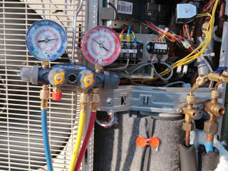
Static pressure reading Now I could close everything off except for a tiny bleed of manifold pressure out the high-side hose end, eliminating the little bit of air in the adapter fitting as I hooked it onto the high-side port.  Another little bit of hissing as I screwed it down as quickly as I could.  There, I was fully hooked up, and with the ball valves open and the manifold valves closed I could now see the pressure of both sides and compare that to my voltmeter box.  This was getting interesting!  Next was to put the system in "filling mode", just to get the compressor running and a little circulation going through the lineset.  [In SkyAir-ese, that's "mode 20".]

Pumping down the lineset One of the steps given around "filling mode" in the service manuals is to close down the liquid valve, and let refrigerant accumulate and condense in the outdoor unit coil and other piping as the compressor runs.  The pressure in the rest of the lineset outside of that valve rapidly decreases, as saturate mix in it gets turned into gas and pulled through the suction line.  This is called a "pump-down", and is a standard industry trick to try and trap most of a system's refrigerant in the outdoor unit and then isolate it behind the service valves, to minimize recovery needed when opening things up for pipe work.  For some reason, the manual sort of says to not do that as such.  Except that's exactly how these systems come from the factory anyways -- with a nominal charge already in the unit as shipped, and the idea being to evacuate just the lineset and indoor parts and then open the valves to let the initial charge into the rest of the system.  So a pump-down really is perfectly valid practice, and was the next thing to play with.
I could regulate this process and the pressure difference by cracking the liquid-line valve open just a little, and finally when I closed it all the way, the compressor kept going until the whole lineset was down to about 25 PSI.  Then I heard a click, and the compressor stopped -- that was clearly the low pressure cut-out sensor at work.  On quickly closing the vapor valve afterward, I could leave the lineset and indoor unit down at way less than saturation pressure, where further recovery would consist of only pulling a little bit of remaining gas out.

One key thing to note here is that the gauge set reads at the lineset on the "outside" of the service valves, and my voltmeter box reads *inside* the unit on either side of the compressor.  This could be distinctly advantageous over what most techs have, where they have less insight as to what's going on in the outdoor unit itself.  Presumably the Daikin "service checker" interface and PC app would have those figures available too.

It was also clearly good to "exercise" the service valves, as turning them felt quite stiff at first and then loosened up as I worked them in and out with the hex wrenches.  It was likely redistributing lubricant over the O-rings where it had been static for six-plus years, possibly leading to a better seal around the valve plungers in general.  Bypass of those could be another potential leak point too.

The next thing to observe was heating mode, for what it was worth, even without quite enough refrigerant present to make it actually work.  Observing pathological failures is just as instructive as observing proper operation.


Pressures during heating mode I would have expected the two lineset pressures in heating mode to be just about the same, minus minor velocity losses through the indoor piping.  But this showed more difference than I expected -- 30 or 40 PSI worth of drop as it came back outside, further supporting the observation that the indoor EXV is also brought into play, to try and slow down indoor coil exit and eke out just a little more heat to the indoors.  The liquid line felt a bit cold, so clearly some gas flashing was already happening as flow arrived back outdoors.

According to the voltmeter box, the real compressor-side suction was down to around 50 PSI and slowly hunting all over the place, as the system strove to find a balance.  Along with that, the "icy finger" would grow and then retreat along that first run of outdoor coil, over and over.  You'd think it would just give up and throw an error after a while.


Dye still present: showed up in gauge hose too After all this playing I brought everything back inside, and happened to observe that my low-side hose had clearly picked up some of the stray dye that was still hanging around at the vapor port.  Hitting it with the UV light really lit that up.  Technically my hoses were now "contaminated" with that, but as it's just dye and not an air/moisture reactive sealant, no harm done.

I finished my playing with around 150 PSI in the gauge set, which rose to around 200 once inside at normal room temperature, and there was clearly a little liquid present in the sight glass if I turned the whole set upside down.  A saturate mix!


  While too much liquid inside a gauge set can be dangerous in the same way an overly hot tank can, this wasn't enough to be a concern.  Next time I used it, I would try to dump most of the pressure back into the running system and leave only vapor inside, and leave a gentle holding pressure to make sure no air got in during storage.

So the next thing was to finish studying up and schedule my 608 test.  This process was rather fascinating, because there was a lot I didn't know about other types of refrigeration systems and correct handling of their contents.  Industrial low-pressure chillers using R-123 or old R-11, for example, run at both above and below atmospheric pressure, and invariably suck in a little bit of ambient air -- and have special "purge units" to collect and eject it automatically!  I learned what those little dead-end copper tubing stubs sticking out of small refrigerator compressors and such are for.  I delved further into what recovery machines can and can't do.  There are all kinds of arbitrary facts on what year certain restrictions kicked in, and how much negative pressure a given size system needs to be recovered to, and even how much a responsible technician or company can be fined per incident of illegal venting to the atmosphere.  Much of it is interesting science; some was just arbitrary cramming that I've already forgotten but could easily look up in the material I collected.  And all of my study material came for free with a little google-fu.

Taking the test was a bit of a saga, leading to one total fail for completely unrelated reasons at the company my buddy had recommended, and then a successful test session at their competition.  And I *aced* the test, only two wrong out of 100, handily earning my "Universal" certification to work on all four types of equipment.  The same shop where I took the test accepted the temporary PDF printout of what my card would look like when I went back the next week, and I drove triumphantly home with a new pink jug of R410A and gave my system the three additional pounds of juice that it had been craving.  Now I could at least cater to its drinking problem without outside help, while continuing to chase the leak conundrum.

As more time went by it was clear that the leak was still present, albeit a little slower than after my buddy had taken his stab at it, so there was some maddeningly variable factor still in play.  Even armed with a better sniffer by now, I was still basically getting nothing on my leak-hunting efforts.  I got a few one-off sporadic readings around parts of the indoor coil, and couldn't quite determine if the UV light spotted a tiny hint of bright green?? buried deep in one section of the finning.  Probing the indoor coil is easier since the air around it can be made absolutely still, and refrigerant tends to drift downward in air.  But those hints weren't consistent, just like for the first tech who visited this thing when the problem first began.  The primary suspects were still elsewhere, however, and one of the purchase cycles from Amazon included the gear necessary to change out the access-port Schrader cores.  The guys responding to my thread at HVAC-Talk agreed that in a system eight or nine years old, the original valve cores could easily be suspect.


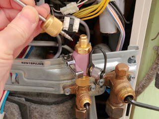
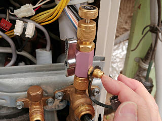
Removing Schrader valve with 'magic tool' I got around to that eventually, using my Appion "magic core tool" in the 5/16" flare variant designed for residential minisplit systems.  [Why those fittings need to be a nonstandard size, I can't imagine.]  This is like a specialized "lockpick" for Schrader valves, relying on just the right amount of grab from a metal fork and allowing removal and replacement without having to empty the whole system.  If the lineset has any meaningful pressure in it, the plunger pushes out *very* aggressively once the valve core is released.  To lessen that, especially on my first try at this, I did another pumpdown so it wouldn't fight me quite as hard.  There's a definite "feel" to practice in knowing when the core is captured, and toggling the ball valve must be done carefully to avoid catching and crushing anything in it.

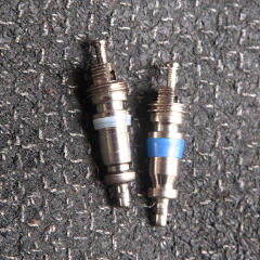
Comparing old and new Schrader cores I compared the factory-original valve versus one from the bag of replacements I'd bought -- a night and day difference, if you ask me.  The factory one had the thinnest, most wimpy body gasket I'd ever seen on one of these, and a fairly weak pin spring, where the new one looked more like what we typically find in a vehicle tire, had a nice snappy action, and a more uniform smooth curve where the plunger seats back onto the end of the body.

'Pffft' test for valve core leak After a new core is in place, the test of it holding is first to make sure the plunger stays put, but also to purge the little bit of air/refrigerant mix that's invariably in the chamber, wait a bit, and give the side valve another little stab to see if it goes "pfft!" at all from any more accumulated pressure.

Nothing visibly moved or leaked while doing either side, so the swap had evidently succeeded.


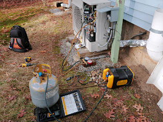
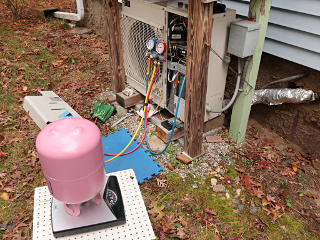
Topping up the system my way Time for another top-up, and to hope that yet another shot-in-the-dark fix would have a more permanent effect this time.  Here's *my* setup for weighing in -- a high-precision scale isn't needed for this sort of thing, just an ordinary bathroom scale on a stable surface.  A trick is to eliminate hysteresis in the reading, by gently pushing down on the tank and letting the scale slowly spring back up to its starting "zero point".  Then, further lightening of the tank will accurately move the scale farther without any hesitation or false readings from internal friction.  It is perfectly possible to read down to less than pound granularity if one is careful about forces and viewing angle.
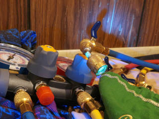
By now I had also added a "vaporizer" to the gauge set, the brass cylinder visible under the low-side blue gauge.  This is a simple device that handles expansion in a controlled way outside of the system itself, in case liquid is being transferred to the low side of a running system just upstream of the compressor.  It helps ensure that slugs of liquid aren't going to enter the system and get pulled into the compressor before it can flash to gas.

_H*   211123