[Each picture is linked to a larger copy.]
There is a common problem with some of the multi-function display (MFD) screens
in the 2004 and some 2005 Prius, manifested by the buttons and the touch areas
on the screen itself becoming sluggish and unresponsive, no display of current
or average MPG, and no control over the stereo or air conditioning.  This
problem tends to start sporadically and slowly become worse over time, although
there have been a few that have failed suddenly and hard.  Another owner who
replaced a failed unit in his own car -- unfortunately, out of warranty and
thus expensive -- was able to keep his old one and kindly passed it along to
me with the intent of possibly finally finding the cause of this problem.
People have been reporting and wondering about this on the forums for quite
a while, and the symptoms seem to be largely the same in most cases.

Toyota knows all about it, as detailed in TSB EL002-05, and their fix is to
swap in a new unit.  But out of warranty, these replacement units are a few
*thousand* dollars from dealers.  There's sometimes an opportunity to obtain
a refurb unit for about $400 - 500.  This is detailed in a Priuschat thread
[copied here] although the Toyota-sourced path is no longer in effect.  If
Autobeyours is out of stock too, what can be done?  Well, after having finally
found the most likely problem cause I can now help the owner community keep
these units going, and with enough persuasion I or Steve or several other
people might be convinced to start a little exchange/repair service.
|
|
|
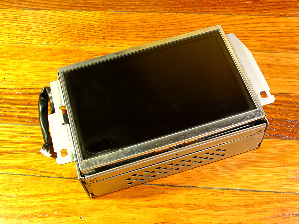
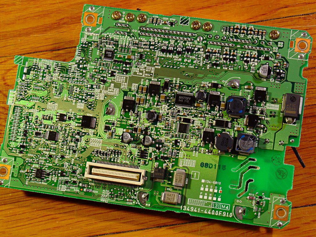
The item in question, front and back.
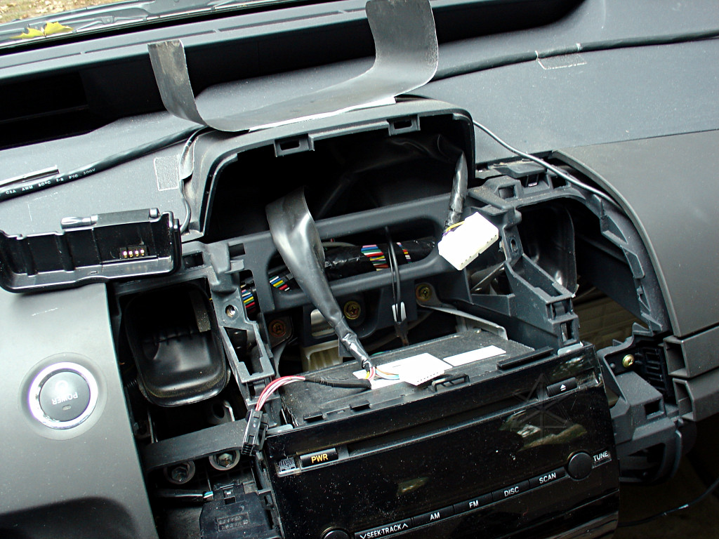
To set up for testing, I had to pull my own MFD out of the mounts, leaving a
large void in the car.  Once the two angled bolts at either side of the unit
are removed, it's pretty easy to snap the whole thing in and out but the
two vent panels on either side need to be left out since the bezel hooks
under them.  That's okay, it's not like my car hasn't spent about half its
life running around with parts of the dash torn apart.  Chris Dragon wrote
a really helpful document about dash disassembly that may be of interest.
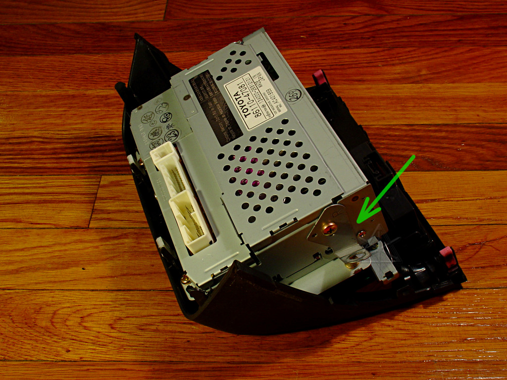
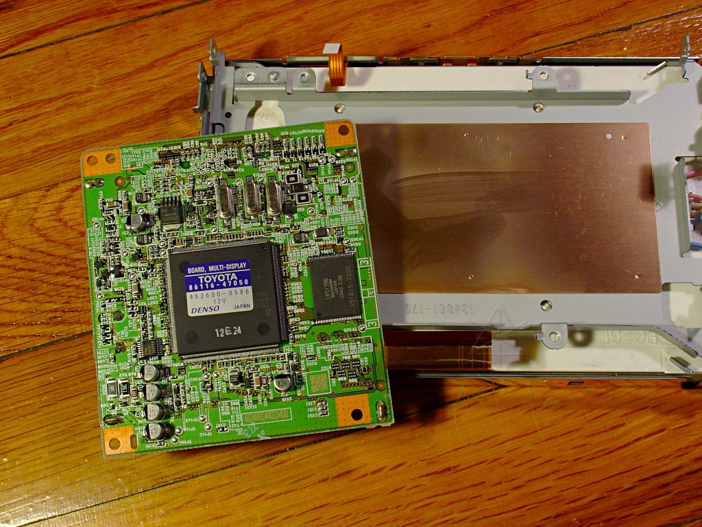
My still-good unit with its button panel assembly.  The angled brackets that
hold the two mounting bolts need to be removed or at least loosened and swung
out of the way to get at two of the MFD mounting screws.
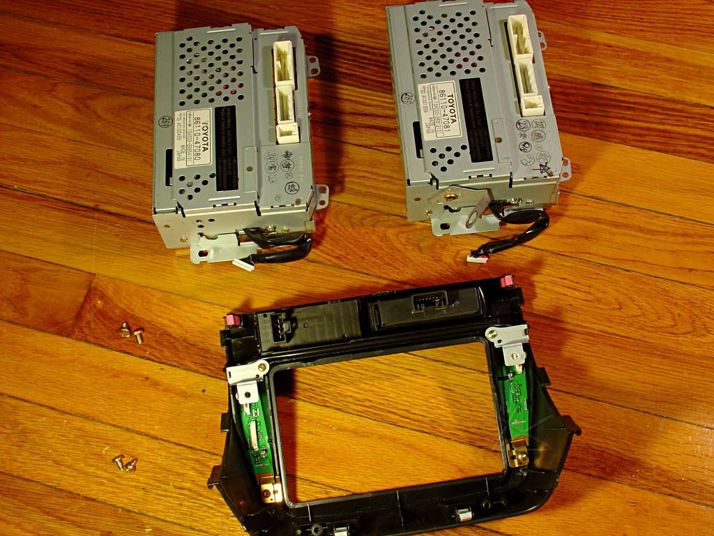
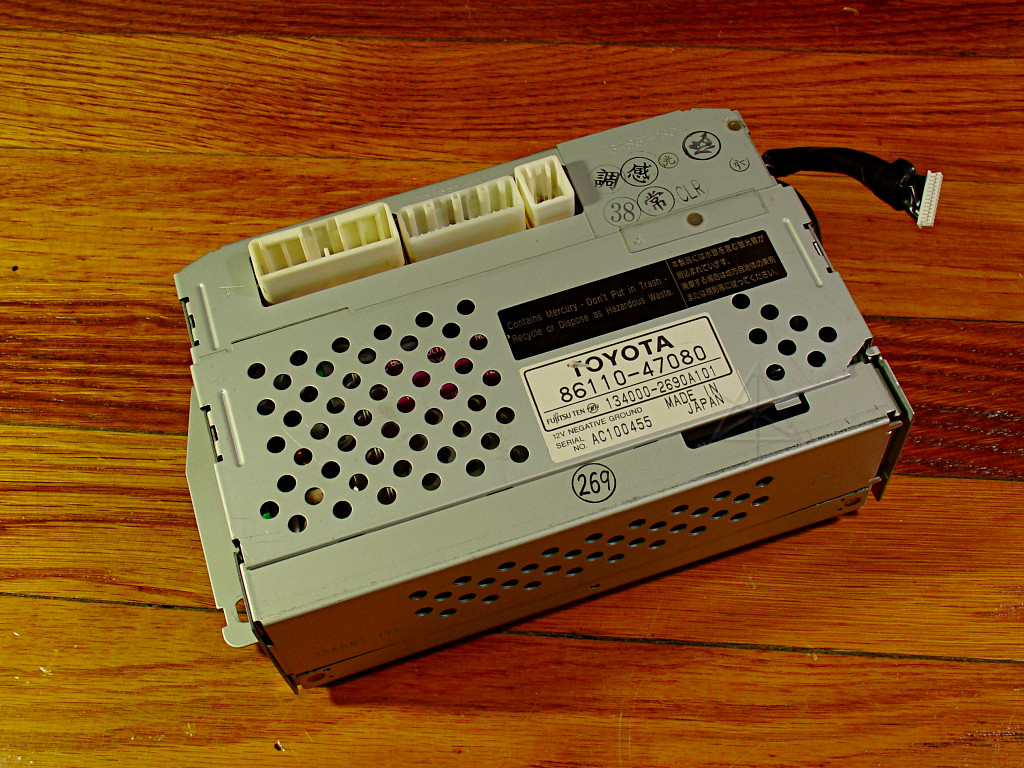
Both units and the empty bezel.  The clock and hazard/odo/trip switch module
are still in place.  These two have slightly different part numbers, making
me wonder if my so-far-non-failed '04 unit might be from a different
manufacturing line or production run.  Hmm, let's take another look at
the TSB...
Well, whaddaya know.  It looks like my unit *is* a ...081, one of the possibly
improved ones recommended as the "current replacement", and the bad one is
presumably outdated.  Analysis of the differences to improve reliability are
detailed on a separate page; see below.
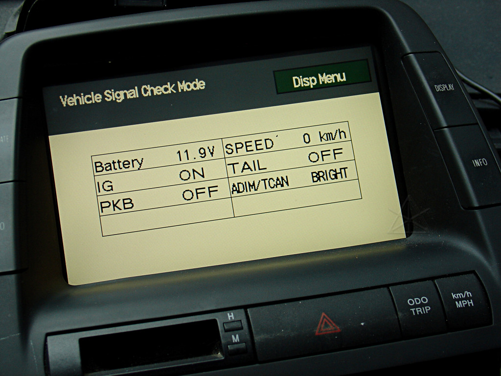
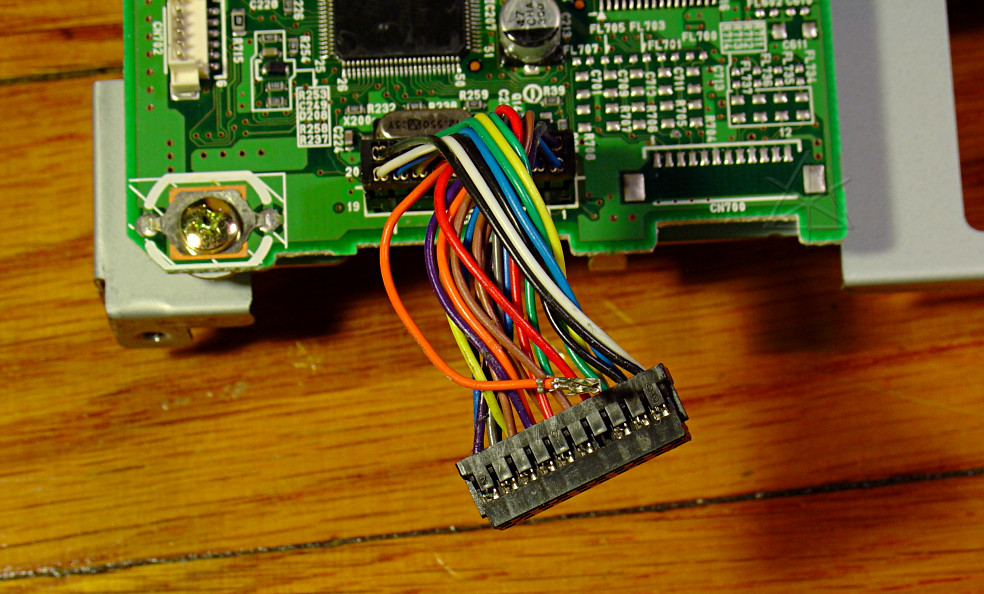
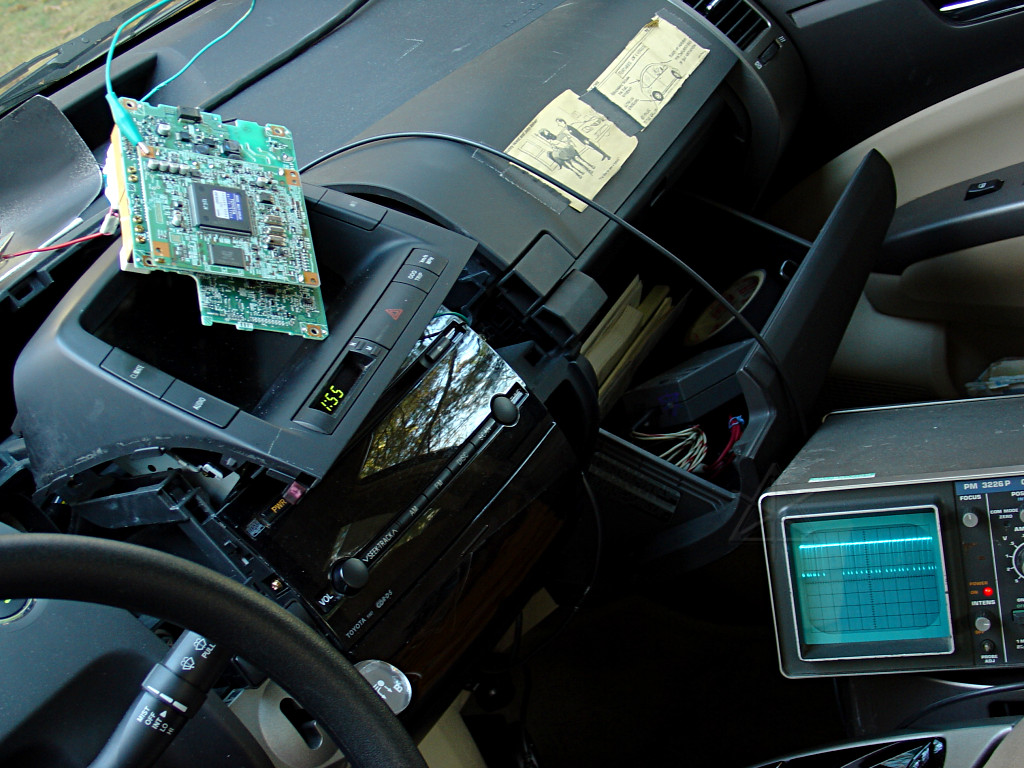
Pre-testing the bad unit.  It powers up and allows entry into the diagnostic
modes, and from here I can check to see what connectivity it still has.  Here
we can see the battery voltage and various other signals that are hardwired
into the harness into the back of the thing.
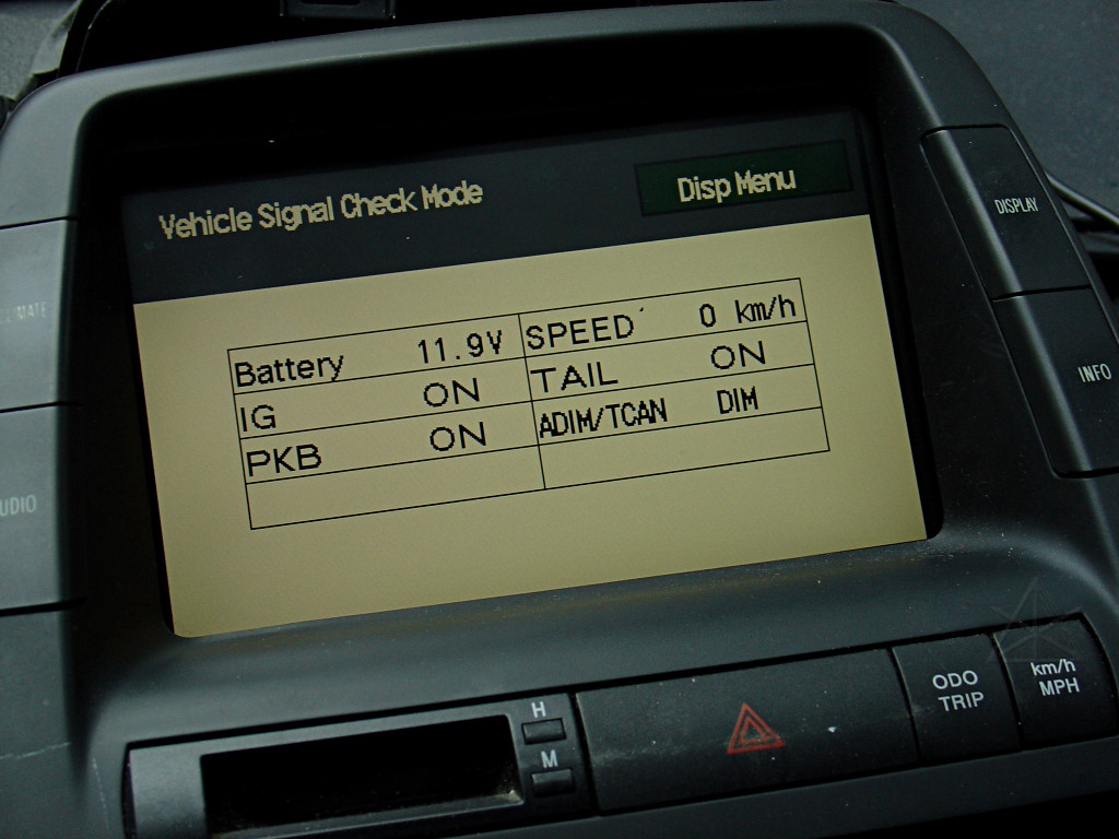
Turning on the running lights causes the unit to dim the screen and change
the displayed state.  I also pressed the parking brake, and the unit sees
that change too.
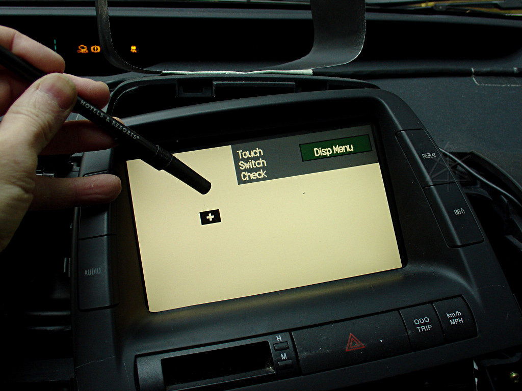
The touchscreen works fine; the little box follows tightly as I drag the
butt of a pen around on the surface.
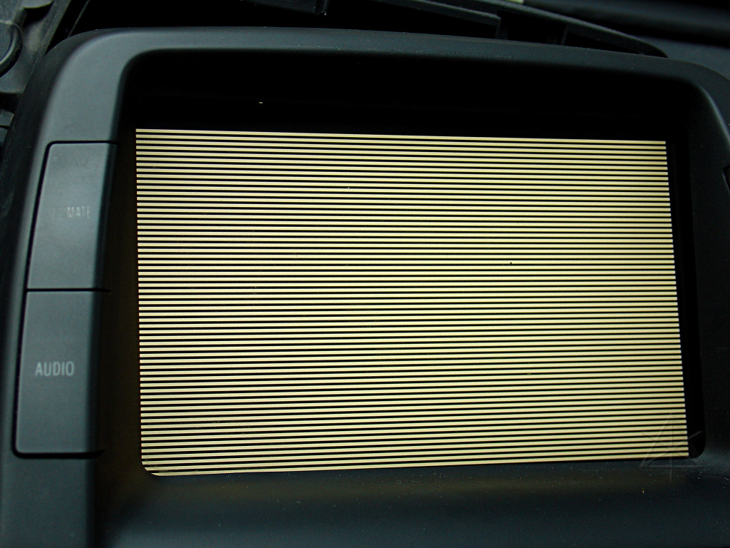
All the single-color and bars video tests are okay.  This picture is likely
to create interesting moire' patterns on your monitor depending on how you're
viewing it.  If you're bored, view the big picture and stare intently into
it while moving your head toward and away from the screen.

The bezel buttons seem to function, responding instantly in the box when
pressed.  However, there is no beeping emitted.  That's significant.
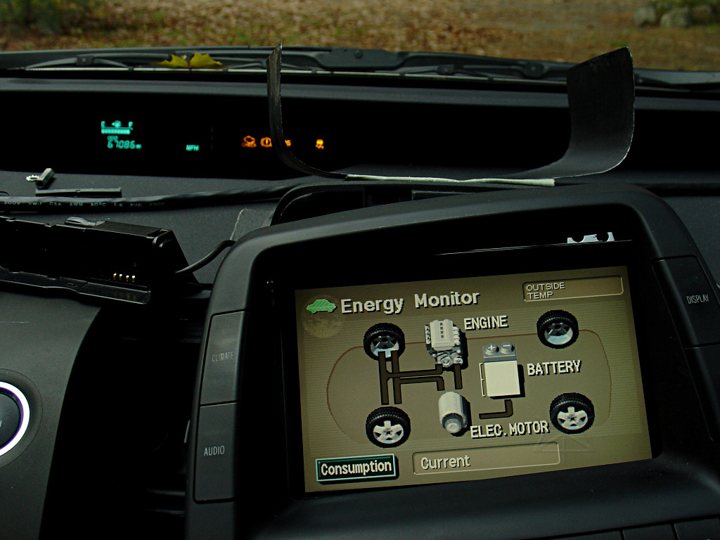
Upon returning to the normal screen, though, we clearly aren't getting data
from the car -- in IG-ON mode here, I should see the battery state and *some*
instantaneous MPG reading even if it's zero with the car not moving.  I can
switch to the consumption screen, but it takes a very long time to respond.

Why?  Because the MFD uses the stereo amplifier to make the button beep -- and
expects a *confirmation response* back from the stereo saying "okay, I made a
beep!"  When that doesn't come back, the MFD eventually gives up and switches
screens anyway.  But waiting for that network timeout is what produces the
"sluggish" response.

Naturally I don't see the MPG average on the consumption screen either,
since that's stored in and sent from the speedometer ECU.
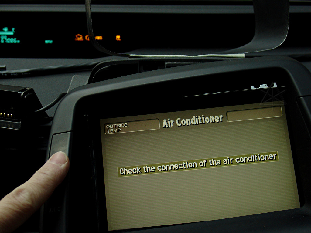
We also can't talk to the climate control system.  All of this matches the
symptoms described in EL002-05 and the forums, and points to the fact that
the AVCLan, a small data network between various components in the car, isn't
reaching the MFD.  [It's actually IEbus, a two-wire network pretty much
designed for the automotive environment.]  Okay, time to figure out where
that comes in and why it's busticated.  At the same time, we'll just get a
good look inside the unit in general.
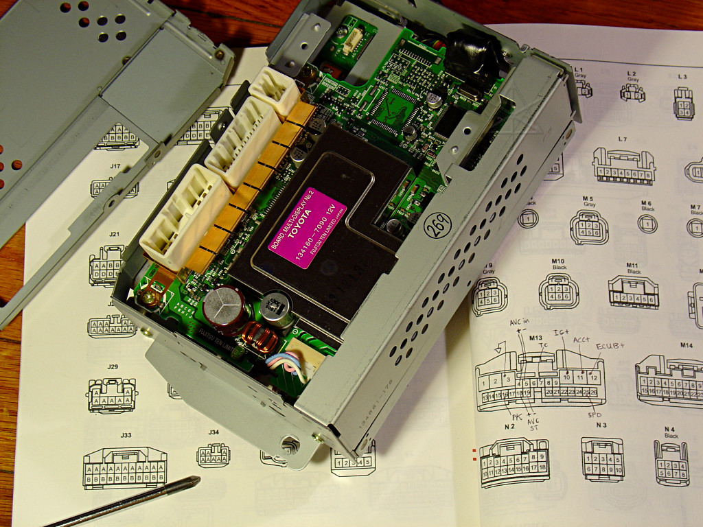
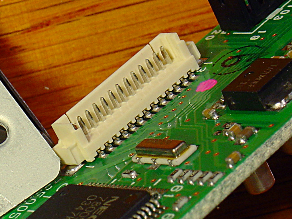
First layer: rear cover removed.  The largest white connector is M13 -- the
main one from the car, and is the one with the connections marked up in the
parts-location bible page shown.  M14 next to it is for the navigation, for
which there's no connector in my non-NAV-equipped car's harness.  The third
connector is completely *undocumented* in the manual.
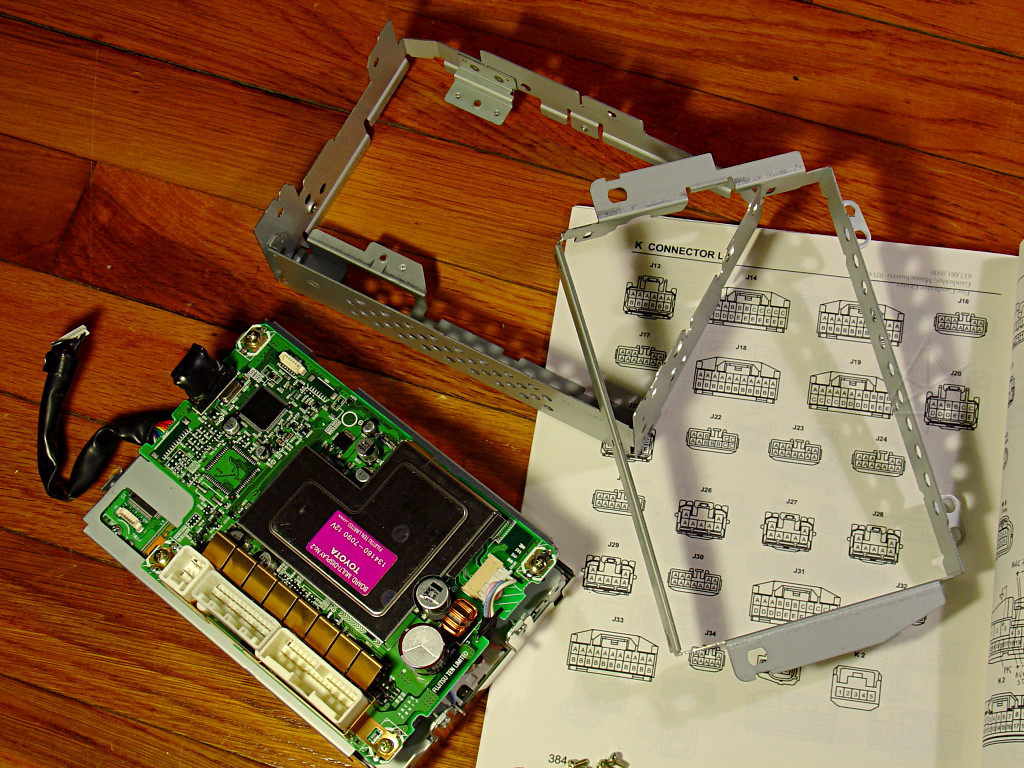
The outer frame of the box comes off next.  There's a lot of sheet metal
holding this thing together, and healthy attention paid to shielding integrity.
The shield soldered onto the board covers a bunch of inductors, and appears to
be a power supply for the electroluminescent panel backlight whose little
white connector can be seen near the right end.
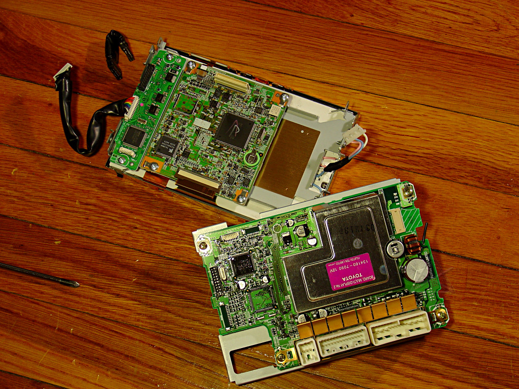
Next, the two halves of the unit split apart into a rear board and the rest
of the display side.  A short jumper connector [U-shaped thing with the
*black* ends, upper left] must be removed first.  The other cable is the one
to the button matrix in the bezel.

During some interim testing, sporadic network connectivity *was* achieved once
in a while, and it seemed to come from wiggling that short jumper connection
or something nearby.  So that's now a prime suspect.
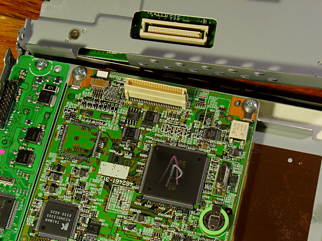
But the majority of connections between the halves appear to go through this
60-pin micro-connector.
|

|
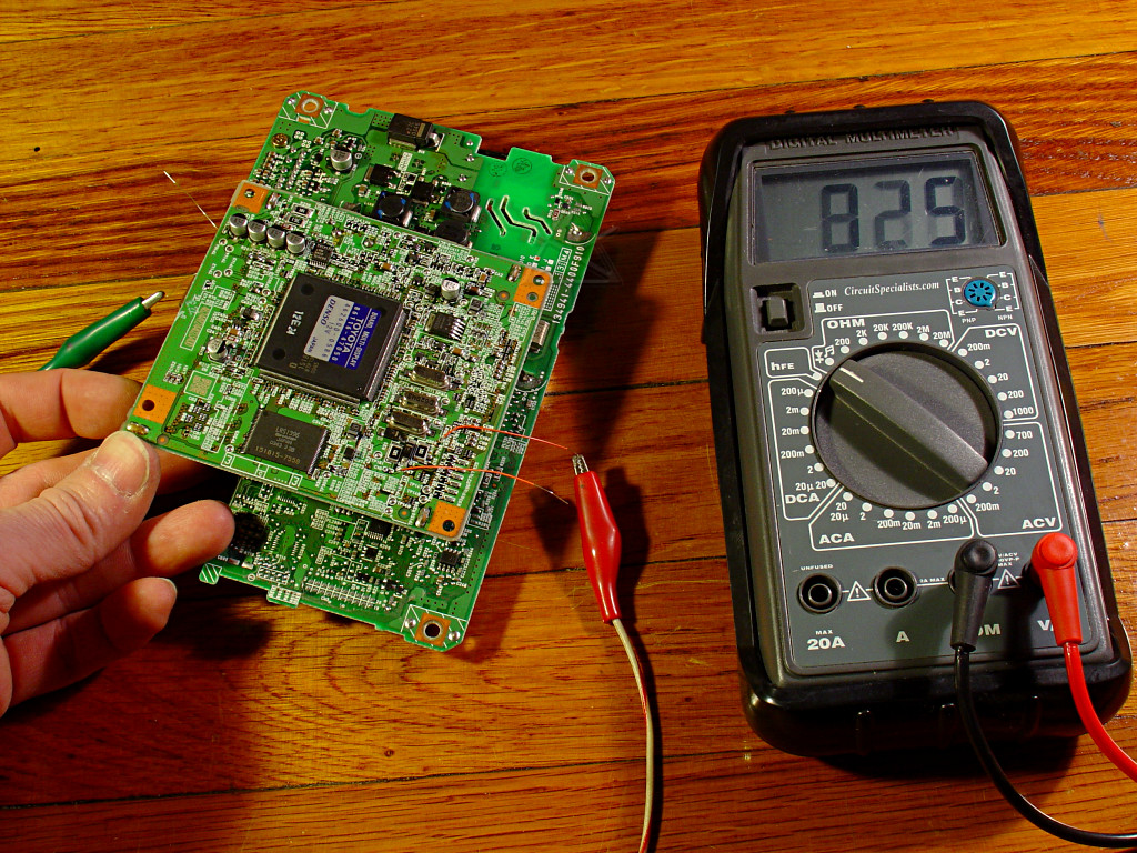
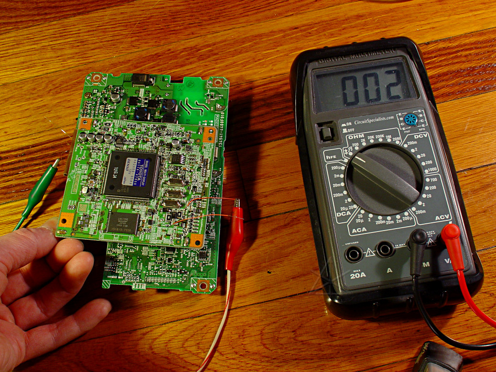
The rear of the outer board.  The area with the black coils is more of the high
voltage power supply for the backlight.  Note how a couple of leads from this
area are isolated by physical slots all the way through the board -- there's
a good reason.  During some bench testing I tried to measure the voltage
produced by this section, and my meter that's rated for 1000 volts shot up
to 1800-something on the highest scale and made a small unhappy noise inside
while a spark jumped to the test lead.  So this area has a couple of KILOVOLTS
running around it, explaining the very widely-spaced connector [barely visible
through the board] leading to the display.  Fortunately, the meter handled
the momentary overload and was undamaged.

It's funny as hell how people worry about a 200-volt battery and orange wires,
and then routinely and voluntarily poke their fingers mere millimeters away
from voltages *ten times* higher on a daily basis without a second thought.

This small board mounts to the remaining half with two screws, but there's also
a little bent-over peg that one edge rests on, presumably to reduce vibration.
There's a plastic pad glued under where the metal finger bears against the
board underneath, and the whole thing is very slightly stressed upward at that
point as evidenced by a compressed divot in the pad.  This prompted close [i.e.
under a 30x binocular microscope] examination of the board to see if prolonged
stress had started any cracks in lands or solder joints, since the suspect
short jumper also connects to this nearby.  But it's only a two-layer board
as opposed to the multilayer larger ones, and looks nominally healthy.
Removing and turning over the final display board reveals the *big* processor.
The ribbon cables going to the screen are brought into nice latch-release
connectors, rather than the limited-cycle force-fit ones we see in a lot
of other products.
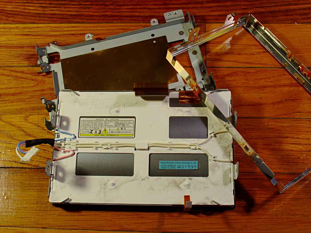
Finally, we're down to the back of the VDU itself.  Note the high-voltage
warning logo; as we've seen, they ain't kidding.  Since going further would
involve unbending metal bits, we'll stop here.  It's pretty clear that the
screen itself is fine, so no need to mess with this.
At this point, everything is getting a cursory pass under the microscope to
look for obvious physical problems.  It's state of the art SMT, and everything
is *very* small scale!  The little jumper cable gets its jacket cut off to
see if there's anything up with the wires or connector pins.  Here's one of
the pins I backed out of the housing to look at, to check if perhaps the
springiness of the lug has weakened.  It appears to be okay and still well
under the width of the mating pins at its rest position, and through the front
of the connectors all the other lugs look okay too.

But the pins themselves appear to have a little bit of pitting right where the
connector fingers bear on them -- hard to tell, it looks worse under particular
angles of light and nonexistent under others.
Same with the smaller connector that goes to the button matrix -- tiny wear
areas.  A pass with DeOxIt and several plug/unplug cycles seems to clean all
this right up, though, so I wouldn't say the connectors are outright corroded.
However, this doesn't fix the problem or even change it.  After a few more
testing cycles, I know several additional things:

	I've reduced what is necessary to reproduce the symptom to just the
	two main boards, naked, thus eliminating the jumper connector and its
	little ancillary board entirely.  The video screen isn't here either.

	I've eliminated the button cable, which was evidently giving some
	false button-press events during early testing stages by picking up
	stray voltage from somewhere.  Probably exacerbated from my other hand
	holding the unit near the VDU high-voltage supply, sending lots of
	nice spikes into open logic inputs.

	I'm scoping the IEbus network leads, and seeing occasional signals
	that look an awful lot like an unterminated data line.  I should
	be seeing something rather different on the scope here.

I can still cause the problem to come and go by wiggling this assembly.  When
the network is working, the signal stabilizes around 2.5 volts with small
deviations when a packet goes by.  When it breaks again, these short spikes
toward ground start occurring and the whole thing jams.  Interestingly, with
the the car's stereo on but at a very low volume level those spikes actually
leak into the audio output a little bit.  That might be a really easy way to
tell if another failing unit is due to the same network-related problem without
any tools: just power up the stereo at zero volume and listen carefully.

I can also hear the difference between a good network and a bad network
on an inductive probe, eliminating the need to hook up the scope every time.
Reducing the test environment to this makes rechecking much easiser, since I
can just plug in, turn on the stereo and wave the probe around near the network
connections and then fiddle the volume or tuning up and down.  This generates
a fast stream of network events which either I hear on the probe's little
speaker, or gets lost in the much louder open-network noise when it all goes
south again.

Twisting the inner display board somewhat clockwise seems to make the network
stabilize, and is now pointing rather strongly to that 60-pin inter-board
connector as the problem area.  There's nothing else that can *move* anymore,
other than trying to flex the boards themselves.  Now, at this point I've
been all over these things under the microscope, and still can't see anything
amiss, but it's definitely a physical-stress related problem.  That's possibly
good, since it's not a failed *part* that would probably need a schematic to
actually debug.
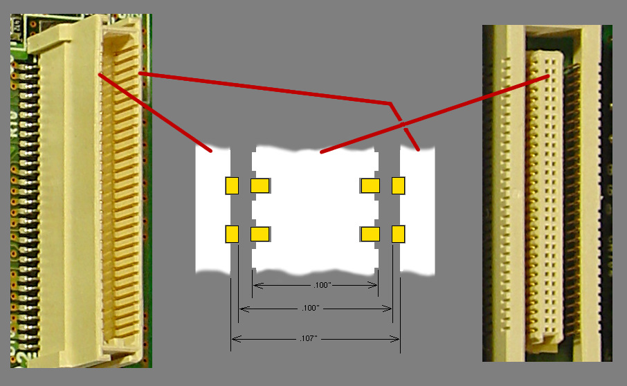
But let's take a closer look at that connector.  All the pins are gold-
flashed, and I see no evidence of the pressure pitting like on the other
connectors.  So connections through this *should* be clean.  However, there
may be a little design problem.  The center "male" piece is connected to
the outer shell via long U-shaped bent leads, and is intended to be able
to float around and adapt to insertion misalignment -- a little of which
will invariably happen when the two halves of the MFD are put together,
since the board mounting positions aren't totally precise!  While the
connections are invisible with the two parts together, a little dimensional
analysis under the 'scope reveals a potential problem.

In this expanded diagram of the connector pieces, the two .100" figures are
NOT a typo.  It looks like the intent is to have a slight interference-fit
mating as far as widths of things go, and let the outer shell's connection bars
protrude slightly into the relief slots in the inner part.  The inner fingers
are supposed to be the sprung elements,  but sit fairly deeply recessed without
a lot of protrusion out of the inner block.  The issue is that the two faces
that align at .100" are going to be *just* flush rather than nested, relying
on the small amount of outward flex of the inner pins to make contact.
Now let's put the pieces together.  The inner fingers touch the outer contacts
and the slight springiness keeps them pressed together.  Great.
But what if the center plastic moves substantially away from center, such as
could happen at each end if one half of the connector gets twisted?  Whoops,
we've just broken contact on one side.
The obvious fix is to allow for more spring movement of the inner fingers,
since the connector's base dimensions seem at odds with how it was likely
*supposed* to work.  This should accomodate more deflection, and is an easy
change I can do to the connector.
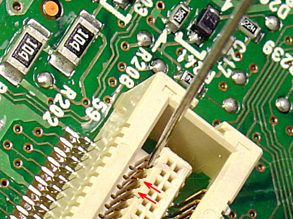
And here's how.  Every one of those sixty pins gets a little tweak outward,
using a small sewing needle under the 'scope.  After doing a couple of them,
note the rest-position difference between the two pins at the red arrows in
the big picture.  After this treatment to all 60, the connector feels a *lot*
tighter when mating, and given that a strongish counterclockwise twist had
been exacerbating the problem, this has *got* to be the permanent answer
short of changing out the connector [yeah, good luck without a serious reflow
station available].
XXXXXXXXXXXXXXXXXXXXXXXXXXXXXXXXXXXXXXXXXXXXXXXXXXXXXXXXXXXXXXXXXXXXXXXXXXXXXX
X                                                                            X
X                                                                            X
X                                                                            X
X                   But after all that, it DOESN'T WORK.                     X
X                                                                            X
X                                                                            X
X    Back in the car, the network problem is still there, and still comes    X
X    and goes when the boards are wiggled relative to each other.            X
X                                                                            X
X                                                                            X
X                                                                            X
X                               WT bloody F.                                 X
X                                                                            X
X                                                                            X
X                                                                            X
XXXXXXXXXXXXXXXXXXXXXXXXXXXXXXXXXXXXXXXXXXXXXXXXXXXXXXXXXXXXXXXXXXXXXXXXXXXXXX

Let's take a closer look at where the network goes.  It comes into the rear
board via two leads [upper pink dots] and then loops through to go OUT again
via two other leads [lower pink dots] that go to the stereo.  Here we can
clearly see that it's a straight pass-thru -- curiously, via two 0-ohm black
chip resistors -- and also has a branch over to one end of the NAV connector.
But where does it go within the MFD itself?  It won't be at all easy to trace
connections physically through this swamp of surface-mount and buried layers
and blind vias, especially when they dive under large parts like the car
connector shells.

But as strange as it seems, the network may actually pass through the 60-pin
connector.  Strange because you'd think the network transceiver would be
placed on the outer rearmost board and tie into some other data interface
to the main processor... but given some of the other oddball parts placement
we've seen around these cars, I guess we have to expect anything.  And it's
easy enough to go after this in the electrical domain.  That same meter that
almost met its doom in the high-voltage backlight supply has one really nice
feature: its diode-test and continuity audible beeper has a *really* instant
response -- faster than any other meter I've used, and fast enough that you
can actually hear "scratchiness" in a moving connection.  And believe me,
milliseconds make all the difference when you're moving through a thicket of
test points trying to find the ONE that's connected to somewhere else.

So by using that and a couple of Very Sharp Probes to get through the conformal
coating, I shortly discover that two pins at one end of the 60-pin connector
do indeed carry the IEbus network through to the inner board.  Two pins located
at one END.  Think about that for a moment, given all the foregoing.
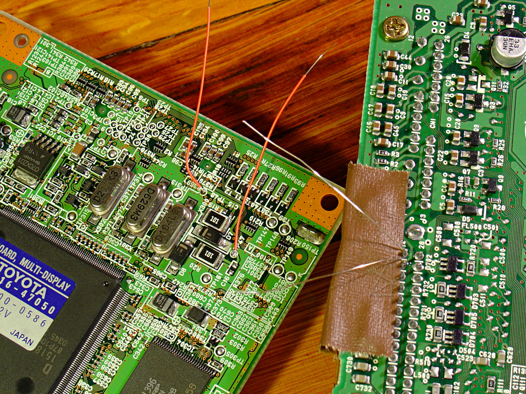
A little more physical tracing follows those two leads up to this area on
the inner board, where they connect to a termination network and present two
handy test points, TP47 and TP48.  Obviously where to check for network
connectivity, huh?  The two leads continue through to the other side of
the board and end at pins 5 and 6 of a small chip labeled CA0008.  Googling
this returns surprisingly few substantial hits -- just a lot of noise from
the datasheet pirates that try to keyword up anything that even remotely
looks like an electronic part number, those fucking parasite bastards.  Kill
them all.  But there are some hints floating around that the chip is the
equivalent of the Hitachi [now Renesas] HA12187 interface driver, documented
here and clearly geared toward "automotive audio equipment".

So here's where to connect a couple of test wires, and to ease testing access
I tack a couple more onto the car-connector pins at the other end.  I'm using
the NAV connector since I'm not as concerned about screwing that one up.
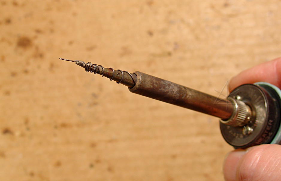
To work in this environment without sweeping broad swaths of dust-sized chip
components off the board from excess heat, I need a very tiny soldering iron.
I don't have one.  So this copper-wire extender for my smallest Weller tip will
have to do.  Not perfect and needs frequent scraping and re-tinning, but I got
my wires on.
One of the connections is solid.  The other is *all* over the place as the
boards are wiggled, and not in any really sensible pattern following how
the connector is stressed -- although the clockwise-twist-to-fix is still
somewhat in evidence.  This is nuts.  I've been all over the solder connections
into this piece several times by now -- they all look smoothly flowed and good.
But now maybe I know where to *really* look.
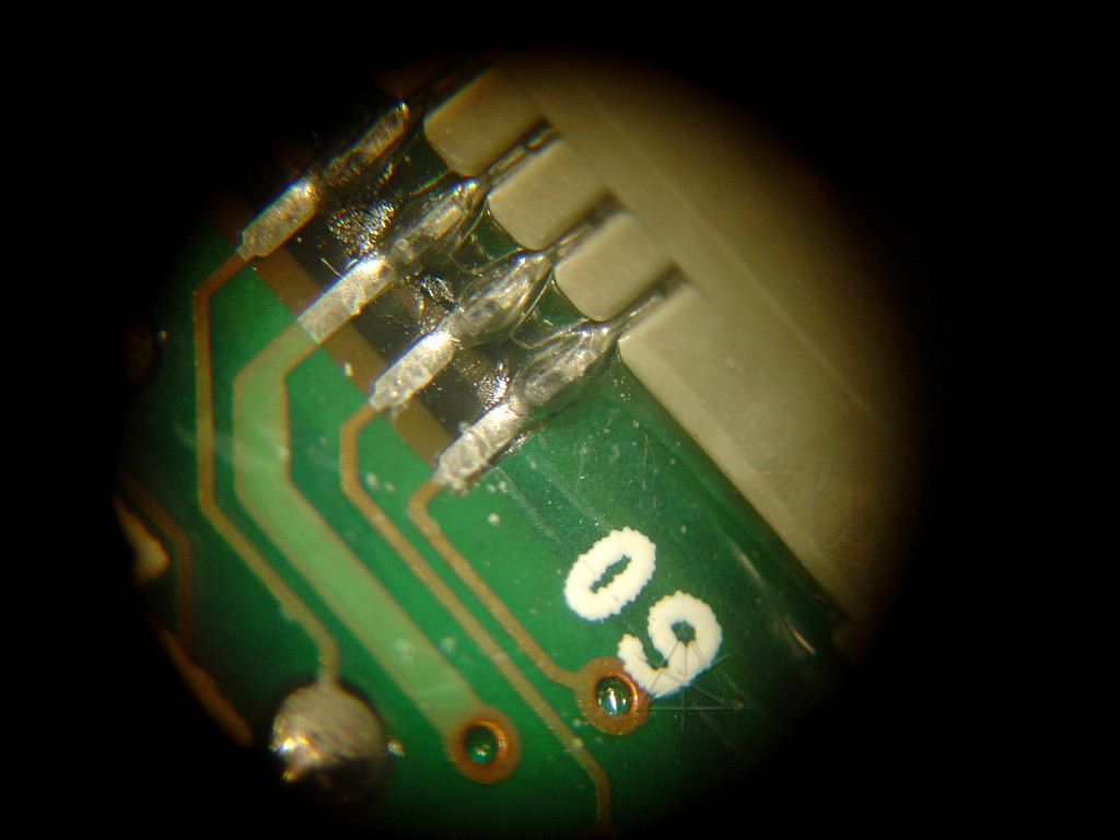
And in the microscope's-eye view, however subtle it may have been to hide until
now, THERE IT IS.  A tiny hairline crack under pin 60.  No, much less than
hairline, since a hair would look like a giant ugly log in this picture or
an even larger magnification.  OMFG, that was hard to find.
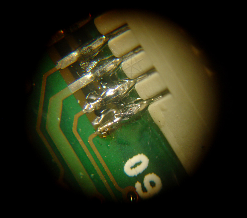
So with my tiny iron and a little bit of my good ol' non-RoHS-compliant "real
men ride Harleys and drink pisswater american beer" 60/40 LEAD-containing
thankyouverymuch solder, I manage to punch through the somewhat excess puddle
of conformal coating around here and reflow both network connections.  I
still can't see anything amiss with the other 58, as tempting as it might
be to try touching up *all* of them.
Retesting shows a solid connection, even under substantial deflection in both
directions.  Beeeeeeeeeeeeeep with no breaks.  Yay.

The "naked boards" setup back in the car yields a solidly working IEbus.

The test wires get removed and the unit gets reassembled, with particular
attention paid to letting the outer board settle into the position of least
sideways strain on the connector BEFORE tightening down the mounting screws.
Once swapped into my bezel, it goes back into the car.  And works perfectly
over several days of testing.
Read an UPDATE written two years later, reflecting
on the Prius community experience
with fixing these things and advancing a new "twist stress" theory on
unit factory
assembly that may also contribute to the problem.
_H* 071117, 071120, and a later update 100124