Daikin self-frying inverter board

  After going through the whole hairball of becoming EPA 608 certified and finally being able to top up my own system, a couple of months after that it was time to go back into cooling season.  I still wasn't sure if the leak was still leaking or what I'd find when firing the system up again, but a quick look at the pressure-equivalent figures said it still had saturation pressure inside and of course I knew exactly what to do if it wouldn't run right.  
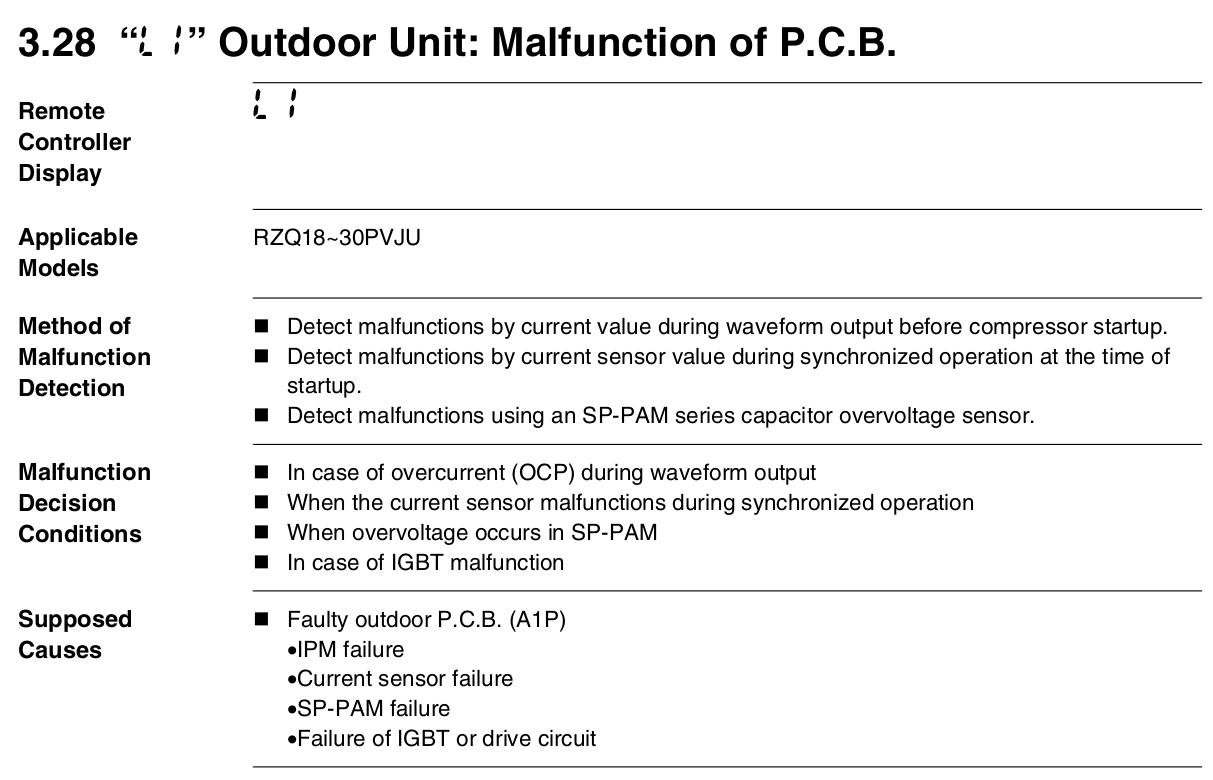
But now it was actually throwing an error, a new one I hadn't seen -- L1.  "Malfunction of outdoor unit PCB".  (service manual pic)

This was trying to tell me that some power module or a current sensor associated with it had gone tango uniform, something not associated with a leak at all.

*Argh.*   Now the fuck what?!

And what would it be next?  Were things getting so generally wretched with this system that it was time to consider just replacing the whole thing?  I wasn't ready for that, and at a minimum wanted to make sure I wasn't looking at a compressor replacement or something like that.

I did a bit of testing, trying to run the compressor in "inverter test" mode where it basically cycles the drive waveform very slowly, enough to see on an LED blinkie-box, and I could feel the compressor *wiggling* a little but not actually running.  So one of the 3-phase legs wasn't getting any current.  Scoping the inverter waveforms was rather inconclusive, just because the output is so noisy and it's hard to find a good ground reference.  Simple ohm checks told me that nothing was obviously open or shorted.  But still the system insisted that the "A1P" board, which is Daikin's common term for main boards in general, was simply bum.  In this case, it's the "everything" board with all the power supply and filtering and control logic and inverter all together, and sits buried fairly far back in the unit with all kinds of harnesses and connectors going to it.

I searched up a handful of technician experiences diagnosing these, notably this post and some Youtubes from guys replacing them in commercial units.  Basically, everything pointed to "just replace the board".  As usual, Daikin's own service people gave me all kinds of crap about being a "licensed contractor", and "what company are you with", and you *have* to basically lie to them to get any support bandwidth from them at all.  They need to learn that some "homeowners" can be as, if not more, clueful than the people working on this stuff every day.  Especially homeowners who get trade certifications just to make their own lives easier.  And now I could confidently tell them that *I* was the tech working on this system including with the refrigerants when needed, which likely carries a little more weight.  The people in the HVACR industry *have* to stop trying to be so damn secretive about the trade, it's not like some elite wizards' guild, and you can learn all this stuff off Youtube and elsewhere anyway.  Daikin's website is also a horror show, and only by jumping through a lot of permission-granting hoops was I able to look up my unit and determine its warranty status.  At nine years old it was definitely out of warranty, so no hope of free replacement parts.  It turned out the same supply house where I took my 608 test could order me a new inverter board from Daikin, given the exact outdoor unit model number, and at a substantially lower price than list.

The more reasonable support guy I finally talked to at Daikin also suggested checking the compressor windings anyway, to make sure that wasn't behind any possible overcurrent situation.  So, back to Amazon to order more tools: this time it was a megger, and in that same order I also picked up the Schrader core tool eventually used near the end of the leak-chasing page.


Meggin' the hermetic, aka 'acid test' On the megger test between the compressor windings and ground, the compressor was actually fine.  And the winding legs all had the same low resistance to each other, so no weird imbalance there.

Normally the megohm, or hipot, test is to help detect acids present in the oil and refrigerant, which tend to increase conduction from coils to surrounding metal and eat away at the winding insulation.  This can eventually lead to the classic "compressor burnout".  Acidity buildup can result from moisture in the system, which is why every technical reference is super-insistent about evacuating below 500 microns to make sure every possible bit of water is boiled to vapor and pulled out.


Top cover removed, harnesses unhooked, rats nest... So I resigned myself to replacing the inverter board, since pretty much everything pointed to that, and began excavating enough to get at it.  The wiring harnesses are run very tightly in somewhat dumb paths around the board frame, and freeing all that up and pulling the connectors led to a bit of a rats nest.  But this would be an opportunity to re-route all that and make it neater.

The inverter board finally out Only a couple of screws hold the board frame and its "reactor" in, as it sort of hooks into place via gravity in the unit.  Finally I had the thing out of there.

The big inductor is just a series filter for the switched DC.

 
  We can't see it here, but there's a largish finned heatsink sticking out the back side of the board assembly, that sits in the airflow from the main fan.  No power devices are visible on the top side of the board, but it is pretty clear from the large lands and isolation gaps where they are soldered in from the flip side.
 
Examining the power devices and heatsink setup Exploring further, after removing a bunch of screws all covered in that obnoxious white heat-sink goop, the board can be separated from the frame and heatsink.  It seems kind of amazing that these fairly small devices, notably the one with the bit of orange tape on it, are what drive the unit compressor.  But when we think about it, it's still less than ten amps, well within the range of typical power modules of this sort.

The paste looked a little dry, but the solder connections all looked pretty good so it wasn't the typical dry-joint problem I'd often find on the legs of main driver transistors in old CRT monitors.  There also weren't any visible "current sensors" as such, so the problem was likely some embedded sensor that's part of a power chip.  On figuring out the bridge topology and doing a little testing, the output section of the big driver actually seemed fine, not open or shorted.


Compare old and new: evidence of running hot In the meantime the new board arrived, and comparing the two confirmed my suspicion around the slight browning at the power device connections.  The old one had evidently spent its share of time at fairly elevated temperatures, eventually leading to discoloration of the flux and board area around them, and ultimate failure of some of the silicon.

  Part of the problem is that there is no external compressor crankcase heater, the system just uses the compressor motor windings themselves, driven in a way that doesn't let it turn, to build up heat in the hermetic.  When the system is on but idle, I can just barely hear something inside keening away at about 10 kilohertz inside, telling me that the inverter is modulating current out to the compressor even when not actively running it.  And stupidly, it does this regardless of ambient temperature -- even in the height of summer, it will continue trying to provide "crankcase heat", and with no airflow coming across the heatsink from the main condenser fan in that state, the board basically just sits in there and cooks itself all day.

No wonder those part connections are brown and the heat-sink paste is dried up.

The system certainly *could* be a lot smarter about this.  There's an ambient temp sensor on the back of the unit, which could easily determine when the outdoors is already warm.  It could also have had a thermistor added specifically for the compressor housing, to tell it that temp, and knock off with the gratuitous self-heating when it's not needed.


What's inside the compressor blanket There's nothing notable inside the little compressor blanket, other than a secondary accumulator and the compressor itself.  Most systems that only do cooling don't even bother with the blankets, since they stay warm enough in summer to vaporize refrigerant out of the oil sump, but it's definitely needed for systems that run in the winter.  Running a cold compressor isn't a great idea.

Compressor stays *hot* even when idle! But the amount of heating done on this one seems a bit extreme.  I left the top insulating pad off for the summer and the jacket a bit loose, so it could actually dissipate a bit more heat since there's no way to simply disable this "crankcase heat" mode.  Since the system doesn't really need to run more than once a day in summer for the cooling/dehumidification and air exchange, I can also just power the outdoor unit down until an hour or two before I run it, usually in the evening when things are a little cooler anyway.

Installing the new board and re-running the harnesses in a better way was fairly straightforward, and that did indeed fix the problem.  Not sure what to do with the old board, or if it's worth trying to do a component-level diagnosis on the thing with no schematic.  I'll keep it around as a potential source of spare parts in case a fixable problem develops on the new one, I suppose, unless it's the same issue after the new board sits there frying itself for a few years.  Because we're frugal New Englanders, we save everything because it "might be useful someday".


  There are a couple of ways to fix this problem, unfortunately in different phases of the product lifecycle.  Newer versions of this same Skyair condenser *do* appear to have external bellyband crankcase heaters, and presumably use those instead of doing the coil-driving trick.  That way an idle inverter board could truly be idle.  But adding an external heater wouldn't fix my existing problem, because as much as I've scanned manuals and asked Daikin support, there's no given way to disable the self-heat mode in this older inverter board.  One possible hack would be to install a muffin fan inside the unit and arrange to power it, to blow air across the heatsink when the main fan isn't running, and thus try to keep the power semis cooler during idle time.  If something like that happens down the road, details may show up here.

_H*   220513, finally writing this up from June 2021