| Part 1: Overview; tires/brakes | |
| Part 2: Underhood | |
| Part 3: Headlights: the Big Schnoz | |
| ==> | Part 4: Inverter pump |
| Part 5: Coolant testing | |
| Part 5b: Engine coolant | |
| Part 6: Transaxle / driveline, references |
|
One increasing concern comes from tales in the forums, all about Priuses
reaching about this age and having the inverter coolant pump fail. It's a
small electric pump that runs all the time and is possibly not quite up to
the long-term task asked of it, as discussed in
this analysis, so when it fails the
inverter assembly and motors can lose significant cooling capacity. The usual
result is the Triangle of Doom and greatly reduced motive power from the
car, most often on hot days, but fortunately this isn't a permanent condition
as there are several thermal safeguards in the system and once it has cooled
back down to sane levels, functionality is restored for a while.
Being rather attentive to the sights and sounds around me where cars are concerned, I realized just from a subtly changed running noise that my own pump was beginning to wear out, almost right on schedule somewhere a little past 100,000 miles. It is possible that mine had a few extra hours on it relative to the car's mileage anyway, as I've spent my share of days with the hybrid system powered up and running to keep some 12V accessories or an AC inverter alive while I answer questions, run demos, and hand out flyers at energy-fests and transportation events. That has put hours on the pump with zero distance, and it wears at the same rate whether the car's rolling or not. Therefore I became a bit concerned about complete pump failure and rising inverter temperatures happening while I was going somewhere, and decided at the very least that for the short term I should be able to monitor the temps in some way. |
|
|
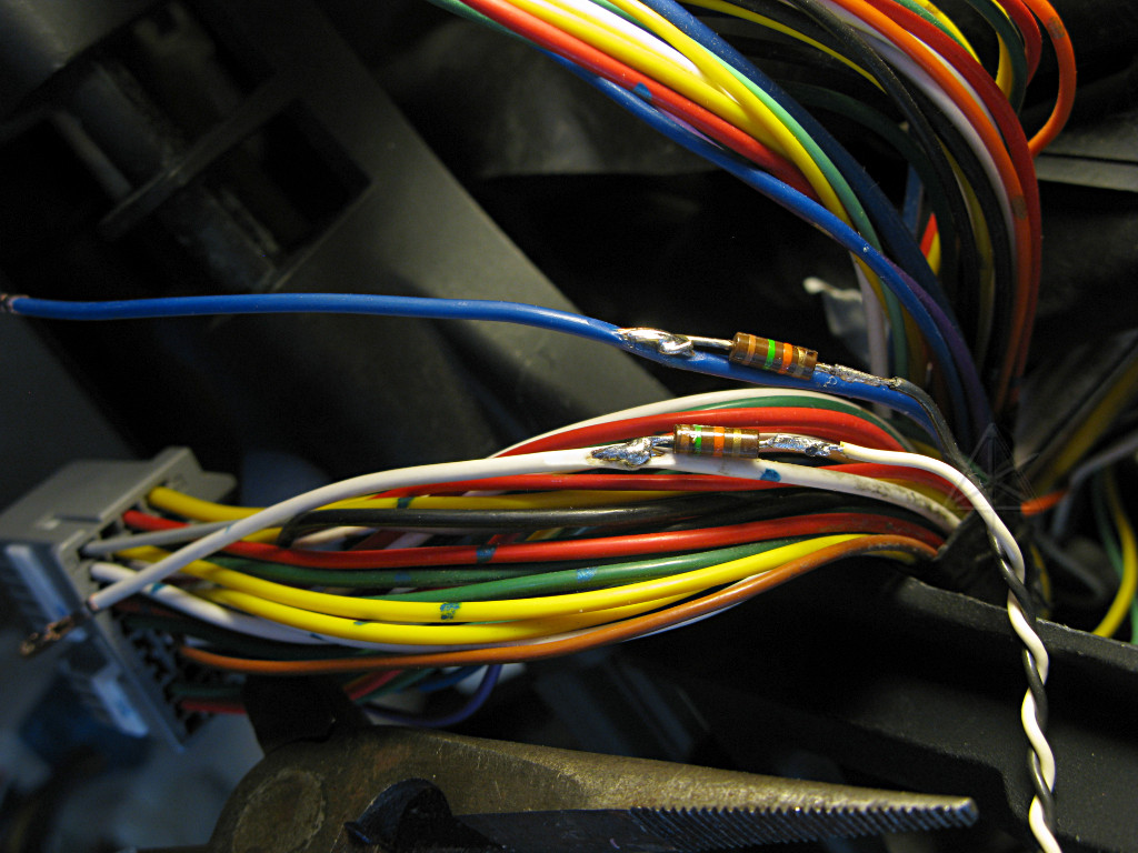
The inverter provides two thermal output signals from its power transistor assemblies, one for each of the racks driving MG1 and MG2 which undergo some very different loading conditions during operation. These signals are not NTC thermistor response curves as for the engine coolant, but are electronically configured to produce voltages that inversely relate to temperature in a vaguely similar fashion. These outputs are more linear and use different scaling, but I figured the easiest thing to do would be to switch them to the same "ECT linearizer" circuit input and just get a relative reading on the meter -- that would be good enough to warn of overheating, without necessarily needing to know the exact running temps. |
|
These two temps are probably the most critical to watch, although the boost
converter and motor windings are also monitored by the ECU for danger signs.
The two signals are thus tapped at the hybrid ECU, straight into resistors comprising one end of a voltage divider. These outputs are driven by low-impedance electronics in the inverter control board, so there is almost no concern about adding a little extra ground load to them. 1K didn't even touch their output levels when temporarily dropped across, and I'm using about 23K total here. |

|
The wires come up to the back of the meter selector rotary-switch and the other half of the dividers which then tie to a ground point. The dividers bring the inverter-temp outputs into a sort of mid-level range for the display circuit, causing the normal nice-weather running temps of roughly 50C to indicate about 5V on the meter. |
|
The actual temp figures can be crosschecked from the hybrid ECU with a
scantool, but aren't necessary to have available all the time. [The
Scangauge community hasn't managed to program Xgauges to monitor any of
these temps via CAN, which could have shortcut a lot of this analog-side
work, but there are some showstopping network protocol issues.] Some testing
was done to determine where the meter reads when temps start rising high enough
to get concerned about, which made for a fun mess of wires and meters hanging
out of the dash for a day or two and a nice demo I took to a local cruise-in
night in the process of running the data-logging.
It was basically there that I discovered that the car could sit powered up with the magic mystery wire that feeds the pump completely disconnected, and that the inverter can dissipate that very low standby load through its own metal mass without the coolant flowing. [See abovementioned analysis for description...] It's always fun to have gearhead muscle-car enthusiasts come by and talk about inverters and ECUs and electric motor control. Which they actually do surprisingly often. When they get curious enough to stick a beefy, tattooed arm down in there to feel the inverter pump running and understand what it's for, you know you've got them thinking a little differently, maybe just for a few moments, before they wander back over to their beloved fire-breathin' iron. | |

|
   ECT tap  <----o===>o------./\/\/\/`----+-./\/\/\/`-------.
                switch        470 ohm     `----^           _|_  gnd
                                             5K pot        ///
As long as I had the gauge panel pulled out for modification, it was an
opportunity to add another little hack I'd been thinking about for a while.
The existing engine-coolant thermistor tap got a small add-on circuit to
manually fake a higher engine temperature as the car sees it, allowing earlier
transition into stage 4 operation and staying in it during minor engine
cooldowns. There's a
Priuschat thread
all about this and why it's nice to have.
This one uses a 470-ohm limiter to avoid driving the faked-out coolant temp
so high that the overheat warnings go on, and the 5K pot gives a larger range
of control which is useful during cold-weather startups.
|
|
Instrumentation enhancements aside, bottom line is that before too long
the inverter pump simply has to be replaced anyway and preferably *before*
it actually fails hard. This means draining the inverter coolant loop,
which also provides the opportunity to refill it with fresh stuff as coolants,
even in relatively light duty, don't last forever either. Once the new pump
and a gallon of Toyota SLLC are in hand, the job is actually fairly easy.
There are several threads and blog entries, on Priuschat and elsewhere, reflecting other peoples' experiences with pump replacement that are well worth reading for supporting/background material. See the references section. There is a definite observable trend toward more "failures" in hot climates like summers in Arizona and Florida. It is possible that some owners have driven around with a failed or dying pump for quite some time in cooler weather, without triggering the overheat warnings! The stories are a mix of DIY and dealer-service, and hopefully providing much more in-depth detail here will encourage more people to handle this repair themselves and save quite a bit on the labor. The inverter can be thought of as something like a really big stereo amp, with enough passive heatsinking around its drivers to handle a nominal load without doing anything extreme, but where one might want to add a fan blowing air over a set of fins for higher-power operation in warm environments. That's sort of what this pump provides -- that extra bit of heat removal. |
|
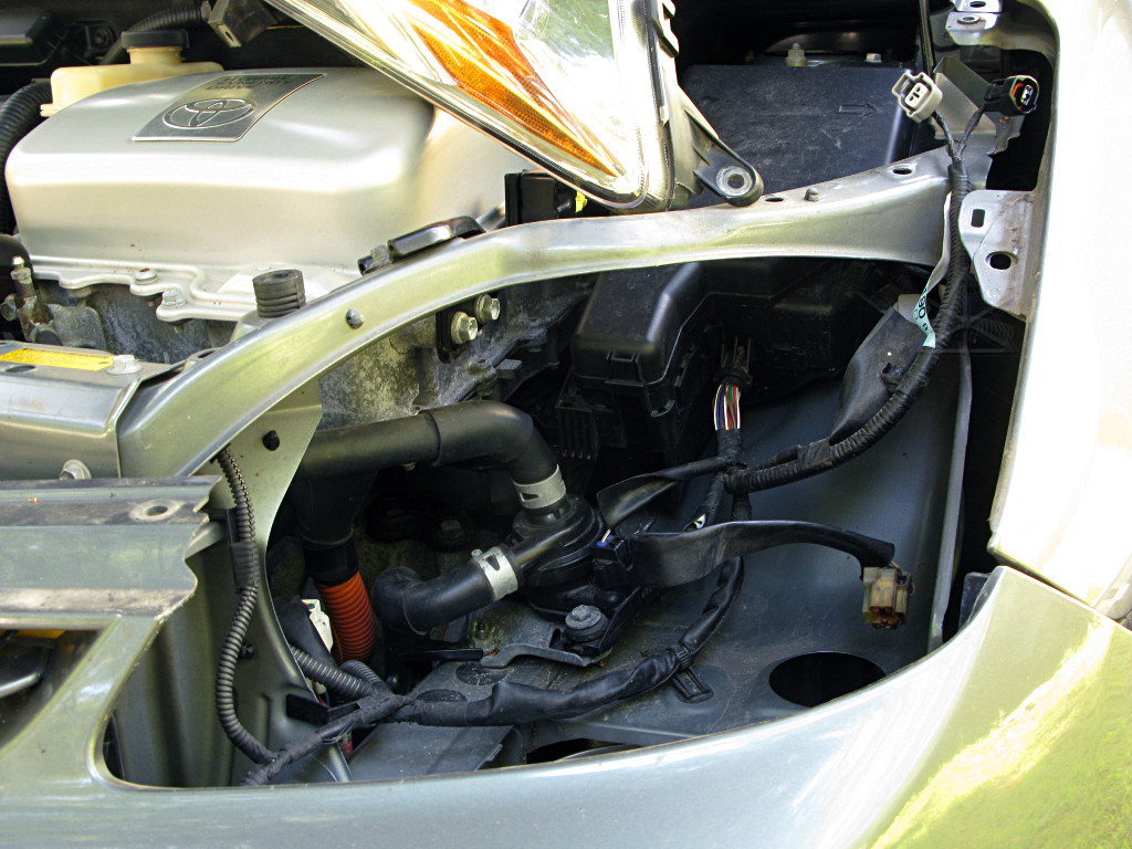
Having the driver's-side headlight out gives very easy access to the pump and coolant hoses. This is why minimalist left-headlight removal was researched in the first place, in fact. Personally, I think Patrick Wong made things much harder on himself and clear photography almost impossible by leaving the headlight in place. |

|
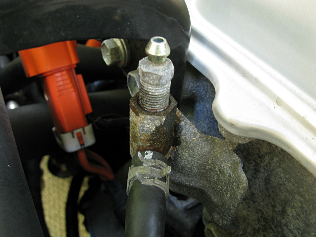
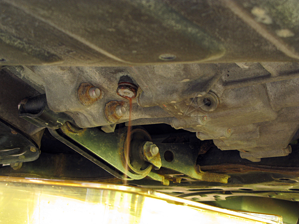
The inverter coolant system has a bleeder for removing air, attached to the front of the inverter. Its hose actually feeds down to the top of the transaxle as shown about midway down the maint50k page. |
|
The bleed fitting is sort of corroded, so a little WD-40 goes onto its threads to soak in for a bit while we're doing other prep work. |
|
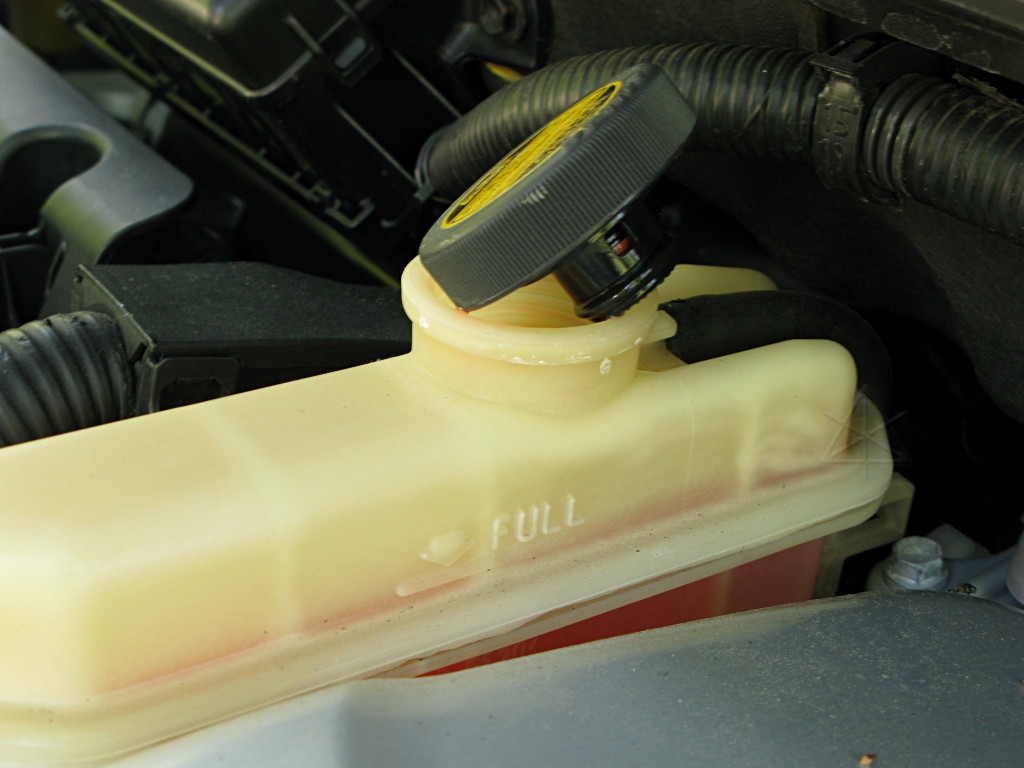
The coolant will drain much better if the reservoir cap is off to let air into the top of the system. |
|
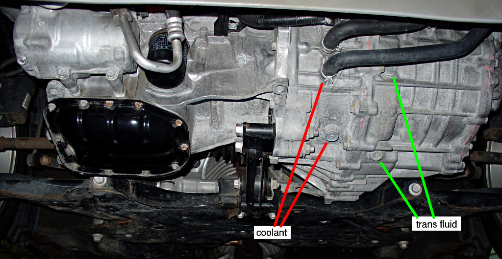
Let's review which fluids go where in the transaxle here. This time we're going after the coolant side. |
|
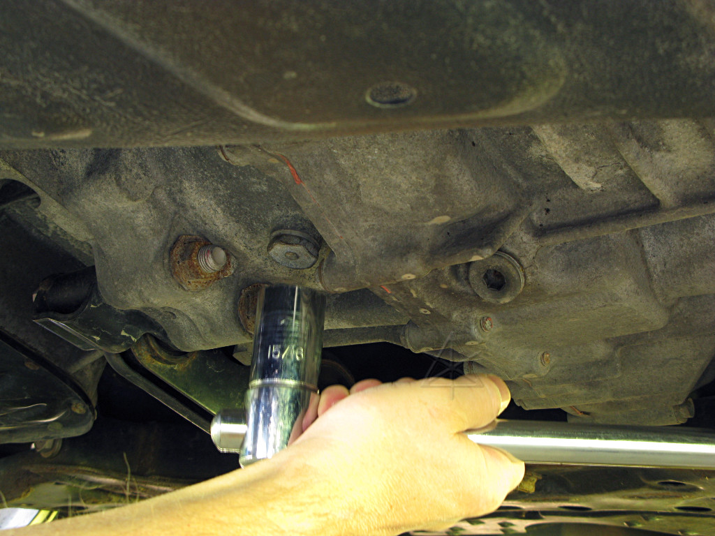
Time to get a wrench onto the drain plug and crack 'er loose. |
|
The coolant is much less viscous than transmission fluid, and starts drooling out around the plug threads immediately. We want to have the catch container under there before loosening. |
|
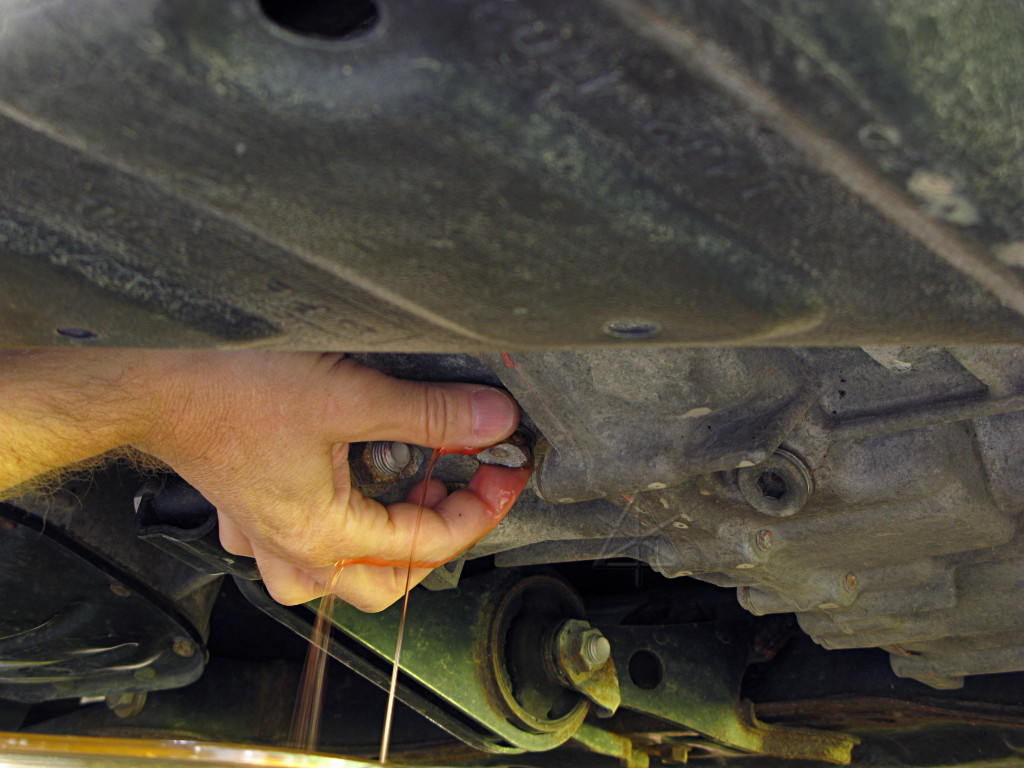
But as the coolant level starts dropping a little and air begins audibly gurgling its way into the inverter passages, a thought occurs. Rather than simply drain it, how about capturing some of the important sounds that are used to indicate success of proper filling procedures? So the plug stays mostly in to just allow a a slow trickle, and I go power up the car to IG-ON to spin the pump. The camera has a sort of laughable sound recorder built into it, which nonetheless may be good enough to capture what happens as more air enters the system and the pump eventually runs dry as the level sinks below its little impeller. |
Play this sound file and follow the timetable below:
| |

|
Now that we're done fooling around, the plug can be opened up to let the
rest of the coolant out faster. Sploosh!
My catch basin is one of the crisper-drawers from the fridge, which had something evolve into sentient brown slime in it and needed to be thoroughly washed out anyway. |

|
The bleed plug doesn't have to be removed completely to let air into the transaxle, just opened a bit; this is just to show what it looks like. It's a needle valve that seats at the bottom with a couple of holes leading into the hollow part up toward the top. Fluid starts coming out the drain even faster once this is open, as the volume near the top of the transaxle can freely flow down. |
|
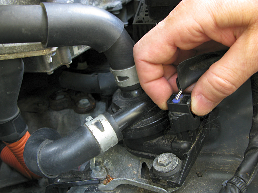
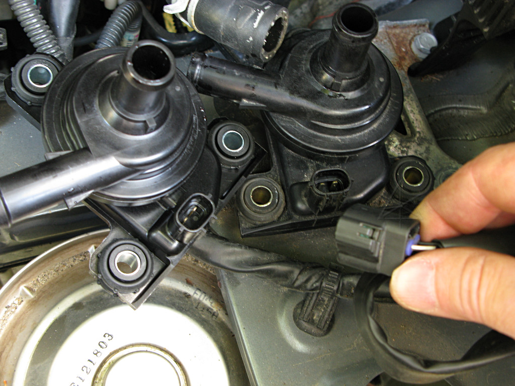
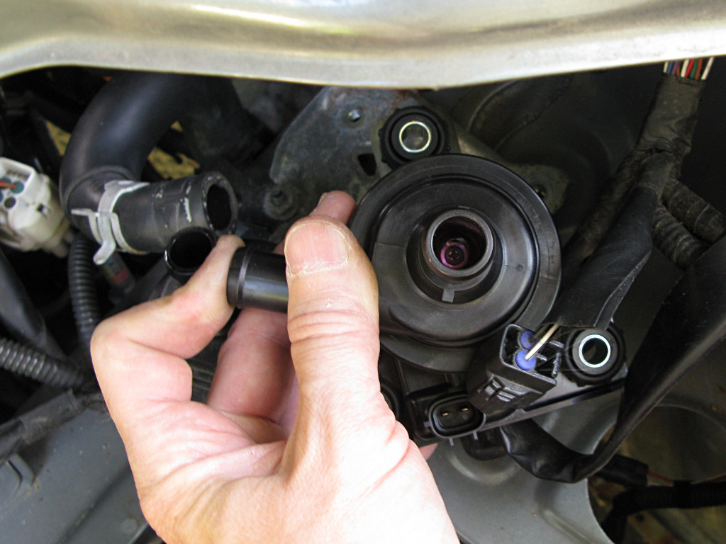
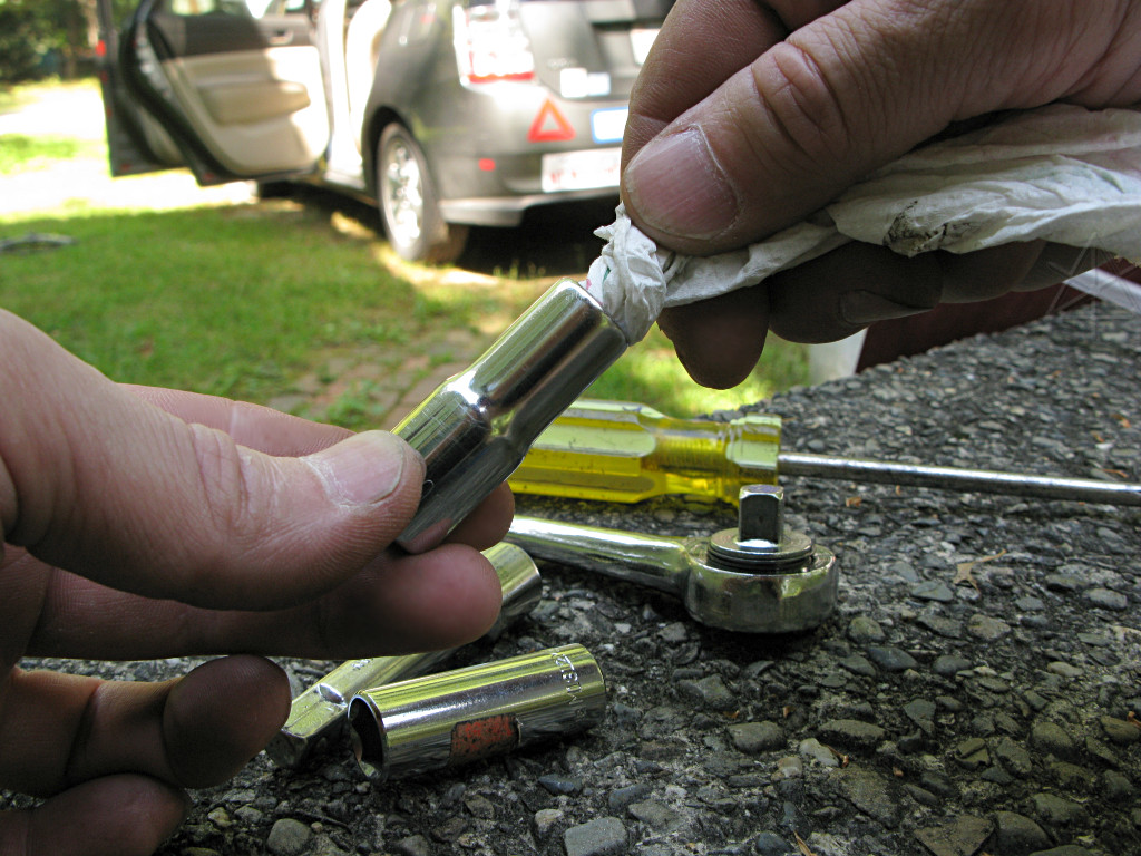
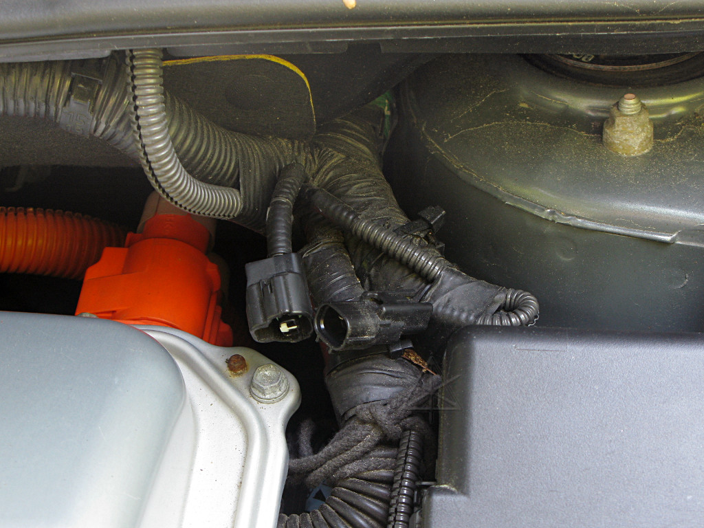
Sometimes the pump power connector is a little hard to remove; squeezing the release tab carefully with needlenose pliers instead of fingers may help. |
|
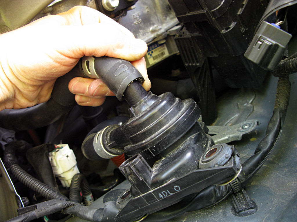
Some helpful assembly worker in Japan somehow managed to put the hose clamps
on with the tabs facing backwards where they're less accessible, so removing
the three bolts holding the pump onto its bracket allows me to swing the
whole thing around and get *my* tools onto the clamps. Once squeezed, they
can be backed up the hose a bit to release from the pump barb.
Prodding underneath with a small screwdriver may help break the hoses loose from the pump, but avoid mangling the rubber. Gently rocking the connected parts back and forth relative to each other works the hose off the barb. |
|
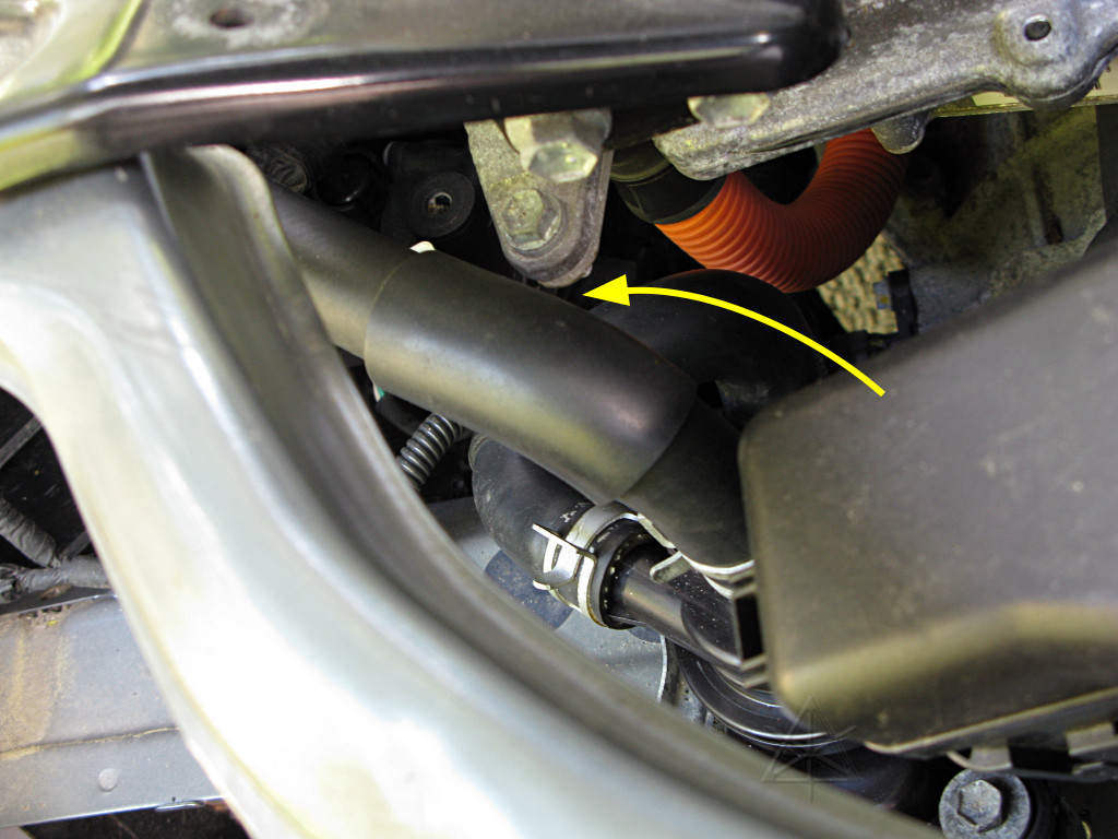
The top hose that runs across the top of the radiator goes down and then up again forming a little valley, and still has a bit of fluid sitting in it. |

|
The lower hose is no problem, since it only goes down from here and that's been all drained out already. |
|
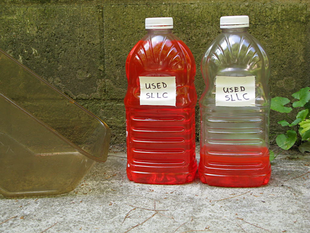
How much coolant came out all told? Eyeballing these 64-ounce bottles says
about 2.4 or 2.5 quarts. Dry spec is 2.9 quarts, so there is possibly
just shy of a pint left inside the system.
Ironically, the spec for coolant capacity is listed nowhere I could find in the '04 or '06 service information PDFs at hand. I eventually found it in my Bentley book. |
|
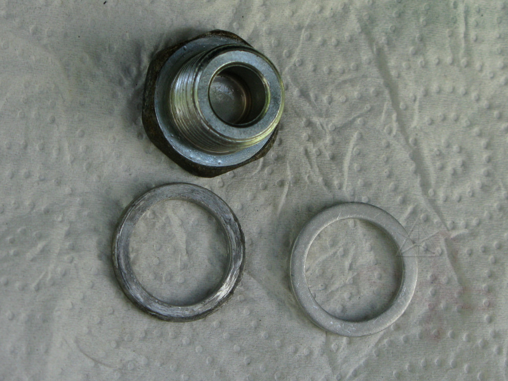
Plug washers, old and new. |
|
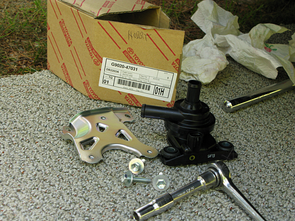
The theory is that the new pump is somehow an improved model. A copy of the
Toyota TSB on it is here, where it is finally
admitted that there might have been a design deficiency. I can see and feel
no particular difference between them other than a very slightly different
molded contour in the casing near the outlet pipe; the new one rattles
internally about as much as the old one when shaken.
It will clearly be easier to mount the new pump onto the old bracket, and this way Steve at Autobeyours [who supplied me the new pump in the first place] gets back an extra brand-new non-mangled bracket out of it to use in his collision repairs. |
|
It's a little disturbing how the new pump seems to have just as much rotor play as the old one, so I want to A/B them running and listen for any differences. However, the new one is dead-dry with no coolant in it at all, and makes a horrible squeaky bearing noise when powered up. The SLLC does have *some* lubricating quality to it, so obviously I have to get both pumps equally wetted with it before this becomes a valid test. |
|
To prime the new pump and get its bearing somewhat lubricated, a little new
SLLC gets dumped in to fill just over the impeller and the pump is run with a
finger over the outlet to keep the coolant in. Much better. I can feel a
little pressure at the outlet, but not a whole lot -- not enough to force
coolant out past a modest grip on the end of the tube, certainly. The pump
is designed to just move fluid around, not pressurize it.
A quick check is done to make sure that impeller retaining screw inside is properly tight, too. Its washer floats just above the end of the impeller bearing, but isn't a precision part and leaves quite a bit of end-play. |
| After both pumps are emptied but now wet with coolant inside, the A/B test is done and the new pump *is* a little less noisy than the old one. So that's some slight confirmation that we're doing a useful swap here. But it's not dead-quiet, by any means -- that little sleeve bearing comes with a fair amount of play right from the factory. It will probably be better once the full load of coolant is in. | |
|
The new pump installed, and hoses reconnected. With the clamp tabs on the *reachable* side now, thankyouverymuch. The upper hose to the inlet should be angled in such a way as to not bear against this corner of the inverter, which would create a rub point. The extra sleeving right there to guard against this shows that Toyota thought about that, but there's no reason to let it touch in the first place. |

|
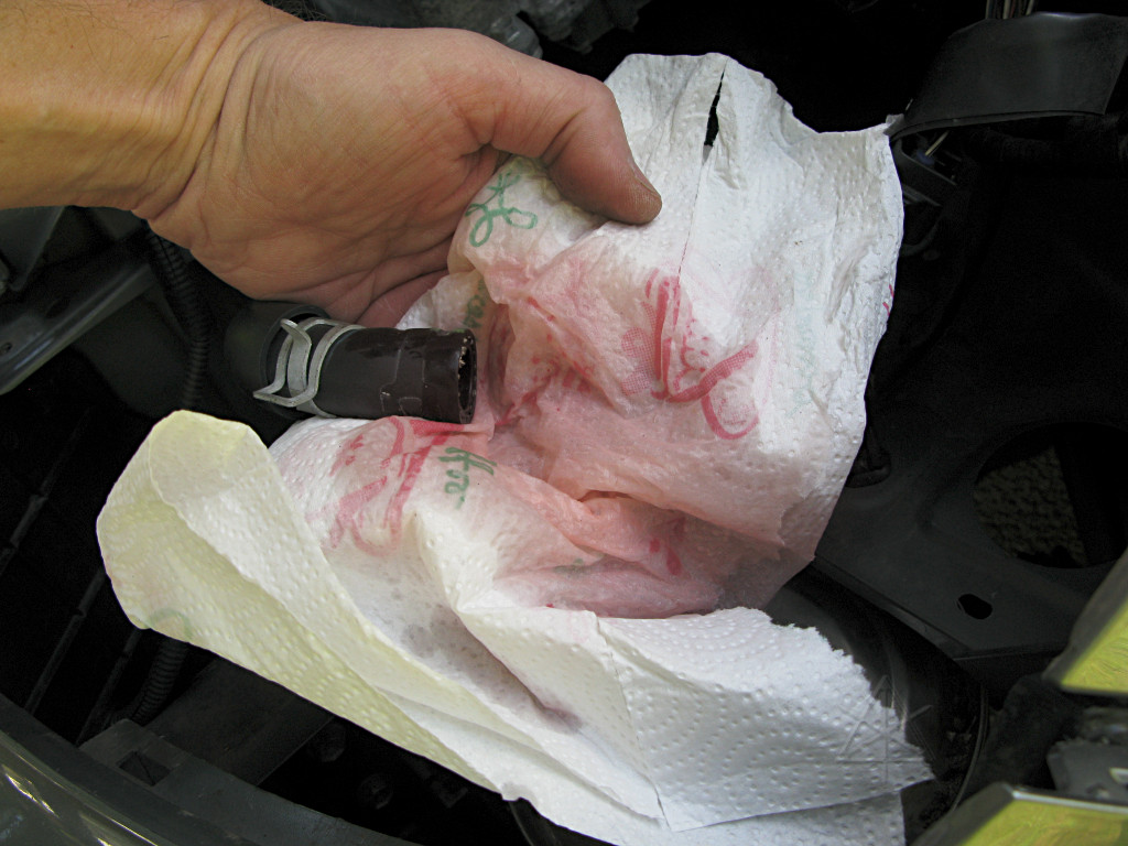
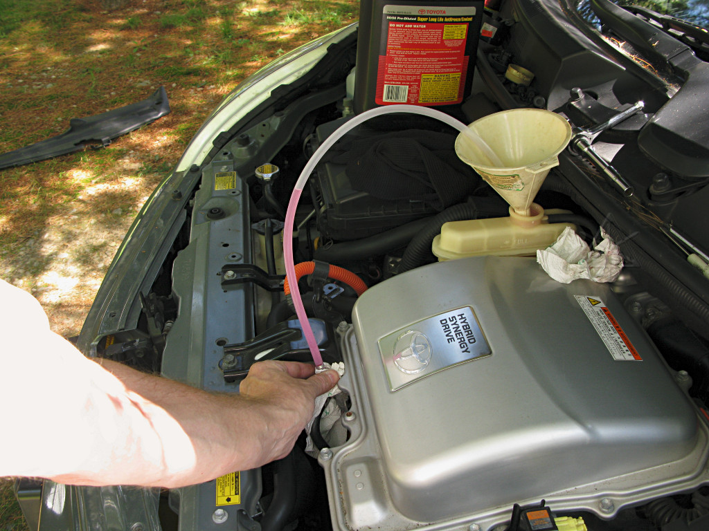
Starting to refill. The overflow hose to the rear of the reserve tank is
brought out to a rag so that any dribble doesn't just fall down on the
transaxle. The funnel helps keep things contained.
The service manual says to fill the reservoir, and turn the car to IG-ON for a while to let coolant circulate, and then turn it off, etc etc. The discovery of the Magic Harness Connector near the strut tower makes it much easier to just leave the car powered up and control pump power from there, as several iterations of running and then letting things settle back are needed to purge all the air. |
| The Bentley book also shows the procedure often used by garage mechanics, using a vacuum tool often called an AirLift. This uses shop air and a Bernoulli orifice to pull a vacuum on the whole system and remove much of the air inside before letting any coolant in, which generally includes letting the hoses collapse flat as the internal pressure gets sucked down. This can't be very good for them, and in addition the vacuum could place undue stress on the inverter radiator, reservoir tank, and the *inverter itself* as its internal cooling passages through the entire center section would also be evacuated. The inverter loop is *not* designed as a pressurized cooling system like the one for the engine. But it turns out, despite a certain amount of paranoia among the DIY community, that simply letting the pump run intermittently and letting the air purge itself out by gravity yields an entirely satisfactory filling job. | |
|
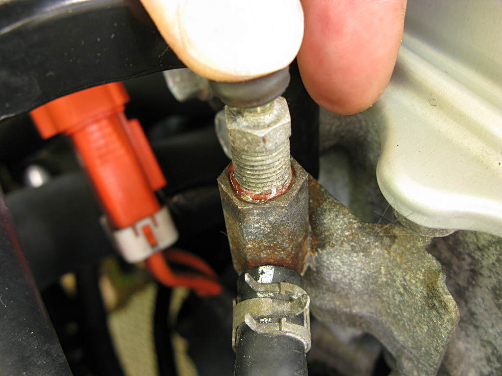
As the pump runs, it tends to push coolant from the transaxle up the bleeder
line about this high. Bubbles appear through it as air leaves the upper
pocket in the transaxle, which will occur on several run/stop cycles.
The bleeder-fitting threads do not seal, so with the needle valve open stray coolant tends to weep out past the threads. Holding a rag tightly around the fitting keeps stray leakage down and catches what does emerge. I hate having coolant dribble down onto engine or radiator parts, as it stays wet for a long time and smells when warmed. |

|
When the pump is stopped, the level settles back to match the level in
the reserve tank. Once no more bubbles appear in the bleed hose right
after each pump startup, the bleeder can be closed.
It only takes five or six cycles of this, with topping up the reserve tank as necessary, to push all the air out of the system and see no more bubbles here or hear any air passing the pump impeller. A little bit of hose-squeezing and shaking gets done to make sure, but doesn't really appear to be necessary. The "full" line and "low" line on the coolant reservoir tank are ridiculously close together, considering that the tank inlet and outlet are down near the bottom. If the level is anywhere near the seam around the top, it's good. |
|
After the bleeder is closed there's still a bit of coolant sitting in its center core and threads, some of which can be forced out by using the little rubber cap as a squeeze-bulb to make some pressure down the center hole and absorb whatever weeps out. Trying to extract the leftover coolant, as little as there is, can't hurt to try to minimize future corrosion as it sits there afterward. |
|
After working around coolants, it's good to clean off the tools and get rid of that weird all-over slippery feeling. |